3. Venting design requirements
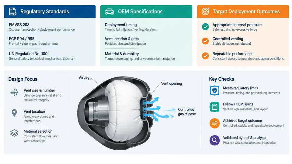
An airbag cushion is a pressure vessel that exists for roughly 100 milliseconds. Its venting strategy determines whether that brief existence produces a controlled deceleration or an injurious pressure spike. Venting design requirements therefore sit at the intersection of three distinct authorities: government regulations that define minimum safety performance, OEM specifications that translate those regulations into component-level targets, and the deployment outcomes the restraint system must achieve across a wide range of crash and occupant conditions. Understanding how these three layers interact is essential before any vent hole, vent panel, or adaptive vent valve can be sized.
The Regulatory Layer: Performance, Not Prescription
In the United States, FMVSS 208 is the governing standard. It does not specify vent area, vent pressure, or gas flow rate. Instead, it prescribes occupant injury criteria measured during instrumented crash tests. The key metrics are HIC (Head Injury Criterion, limited to 700 for the 50th-percentile male in a 56 km/h frontal rigid barrier test), chest deflection (limited to 63 mm for the same dummy), and neck injury criteria. For out-of-position (OOP) occupants, FMVSS 208 includes low-risk deployment (LRD) tests in which a small female dummy or child dummy is positioned close to or against the airbag module at the time of deployment. These tests impose strict limits on neck force and moment, directly constraining how aggressively the cushion can pressurize.
In Europe, UN Regulation No. 94 and the broader UN R94/R95 framework establish similar frontal and side impact requirements, while Euro NCAP goes further with its own rating protocols. Euro NCAP's frontal offset test (50 km/h, 40% overlap against a deformable barrier) and its mobile progressive deformable barrier test create different loading profiles than FMVSS 208, which in turn shifts the optimal venting balance. A cushion tuned only for a rigid barrier may vent too slowly for an offset deformable barrier, where the occupant loads the bag asymmetrically and a slower-venting cushion can produce excessive chest compression on the struck side.
China's GB 11551 and the C-NCAP protocols add another layer, with specific OOP test matrices that differ in dummy positioning and temperature conditioning. The practical consequence is that a venting design intended for global platforms must satisfy the union of all applicable regulatory envelopes, not just the most permissive one.
OEM Specifications: Translating Regulation into Hardware Targets
OEM specifications convert regulatory pass/fail criteria into measurable component requirements. A typical OEM venting specification will define the following parameters:
- Vent area (Avent): The total effective open area of all vent features, expressed in mm². This may be a single hole, a pattern of holes, a fabric panel, or a variable orifice.
- Vent coefficient of discharge (Cd): A dimensionless factor (typically 0.6–0.9) accounting for flow losses through the vent geometry. It is determined empirically and is critical for accurate simulation.
- Opening pressure threshold (Popen): The internal pressure at which a vent panel or valve begins to open. For passive vents, this is the pressure at which the fabric seam or tear seam ruptures.
- Mass flow rate (ṁ): The rate at which inflation gas exits the cushion, often specified as a function of internal pressure and temperature.
- Temperature range: Venting must be validated from −35 °C to +85 °C. Cold gas is denser and vents more slowly; hot gas is less dense and vents faster. The same physical vent area produces different pressure histories at temperature extremes.
These parameters are not independent. Increasing vent area reduces peak pressure but also reduces the cushion's ability to absorb energy through internal pressure work. Decreasing vent area raises peak pressure and increases the risk of OOP injury. The OEM specification typically provides a target pressure corridor — for example, a driver-side frontal airbag might be specified to reach 250–350 kPa peak internal pressure within 30–40 ms at 23 °C, then decay to below 50 kPa by 120 ms.
Example OEM venting specification (illustrative values for a driver-side frontal airbag):
| Parameter | Target | Validation Method |
|---|---|---|
| Vent area (total effective) | 1,200 ± 100 mm² | Physical measurement, CT scan |
| Discharge coefficient | 0.75 ± 0.05 | Flow bench, pressure decay test |
| Peak internal pressure (23 °C) | 280 ± 40 kPa | Instrumented tank test |
| Time to peak pressure | 35 ± 5 ms | Instrumented tank test |
| Pressure at 120 ms | < 50 kPa | Instrumented tank test |
| OOP neck force (3-year-old, LRD) | < 1,500 N | FMVSS 208 LRD test |
Target Deployment Outcomes: What the Cushion Must Achieve
The ultimate purpose of venting is to shape the cushion's pressure-time history so that the occupant's kinetic energy is dissipated at a rate the body can tolerate. This translates into several target outcomes:
1. Sufficient initial stiffness for occupant coupling. In the first 20–30 ms, the cushion must pressurize quickly enough to engage the occupant before they travel too far forward. If venting is too aggressive, the cushion remains soft, the occupant "bottoms out" against the steering wheel or instrument panel, and chest deflection exceeds limits.
2. Controlled pressure decay for energy absorption. After peak pressure, the vent must allow gas to escape at a rate that matches the occupant's deceleration. The cushion acts as a spring-damper system: internal pressure provides the spring force, and venting provides the damping. The venting rate determines the damping coefficient. Too little damping (small vent) produces a stiff, bouncy cushion that rebounds the occupant; too much damping (large vent) produces a soft cushion that collapses under load.
3. OOP injury mitigation. For occupants positioned close to the module, the cushion must deploy with limited force. This is often achieved through adaptive venting: a tether or valve that opens early when the occupant is detected in close proximity, reducing internal pressure during the critical first 10–15 ms. The target is to keep neck force below regulatory limits while still providing adequate restraint for the in-position occupant.
4. Robustness across conditions. The venting design must perform consistently across temperature extremes, occupant sizes (5th-percentile female to 95th-percentile male), and crash severities (low-speed 25 km/h to high-speed 56 km/h). This robustness is validated through a matrix of physical tests and correlated simulations.
Practical Implications for Venting Design
The three-layer framework has direct engineering consequences. First, venting design cannot begin until the regulatory and OEM target envelopes are fully defined. A vent area that satisfies FMVSS 208 may fail Euro NCAP's offset test because the loading profile differs. Second, the venting specification must be expressed in terms that can be measured and verified — vent area, discharge coefficient, and pressure-time history — not in vague terms like "adequate venting." Third, the target deployment outcomes must be validated across the full operating matrix, not just at nominal temperature and a single crash speed.
A common failure mode in venting design is optimizing for a single test condition. For example, a cushion tuned to pass the 56 km/h rigid barrier test at 23 °C may produce excessive neck force in the −35 °C OOP test because cold gas vents more slowly, raising internal pressure during the critical early phase. The corrective action is typically to increase vent area or introduce a temperature-compensating vent feature, then re-validate the full matrix. This iterative process — specify, test, adjust, re-test — is the practical reality of venting design, and it is driven entirely by the requirements hierarchy described above.
Design tip: When specifying vent area, always define it as effective vent area (Aeff = Cd × Ageometric). Two vents with the same geometric area but different edge conditions (sharp-edged vs. radiused) will produce different discharge coefficients and therefore different pressure histories. The effective area is what the simulation and the physical test must agree on.
In summary, venting design requirements are not a single number or a single test. They are a hierarchy: regulations set the pass/fail boundaries, OEM specifications translate those boundaries into measurable component targets, and the target deployment outcomes define what the cushion must actually do to the occupant. A venting design that respects all three layers — and validates against the full operating matrix — is the only design that can be released with confidence.