1. Airbag venting fundamentals
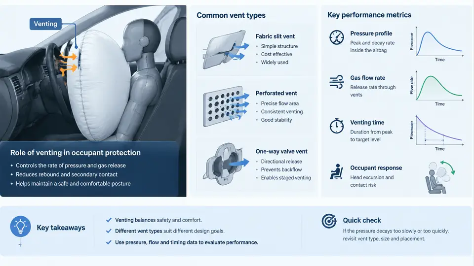
An airbag is not a sealed cushion. It is a controlled gas-release device that happens to inflate. The inflator delivers a large mass of gas in tens of milliseconds; the vent system then removes a precisely tuned fraction of that gas so the bag can absorb the occupant's kinetic energy instead of returning it. Designers often describe the vent as the "tuning knob" of the restraint: change the vent area by a few hundred square millimeters and you can shift peak chest acceleration, bag internal pressure, and occupant rebound simultaneously. This chapter establishes the physical role of venting, the main vent hardware families, and the metrics used to judge whether a vent design is acceptable.
1.1 The Energy Balance Inside the Bag
During a frontal impact, the occupant moves forward at the vehicle's pre-crash velocity (for a 56 km/h barrier test, roughly 15.6 m/s). The airbag must decelerate the torso and head over a limited stroke — typically 150–250 mm of bag compression — while keeping the occupant from "bottoming out" against the module or steering column. The governing relationship is a mass-and-energy balance:
m_occ · Δv  =  ∫ (P_bag − P_ambient) · A_contact  dt

where:
  m_occ      occupant effective mass (kg)
  Δv         velocity change absorbed by the bag (m/s)
  P_bag      instantaneous bag gauge pressure (kPa)
  A_contact  projected contact area between occupant and bag (m²)
  t          time (ms)
Venting controls P_bag. If the vent is too small, pressure stays high, the bag behaves like a rigid surface, and chest acceleration (a3ms) rises. If the vent is too large, the bag deflates before the occupant's head reaches it, and the head can strike the steering wheel or A-pillar. The design target is a pressure–time curve that peaks early, then decays in step with occupant penetration.
1.2 Vent Types and Their Behaviour
Production airbags use four vent families, often in combination:
- Permanent open vents (fabric orifices). Die-cut holes or woven gaps in the cushion, typically 20–60 mm diameter, one to four per bag. They provide a fixed, predictable leak path. Cheap and repeatable, but they cannot adapt to occupant size or crash severity.
- Pressure-relief / burst-disc vents. A sewn or bonded seam that ruptures above a threshold pressure (commonly 30–60 kPa gauge). They keep the bag sealed during the initial inflation spike, then open to prevent over-pressure. Useful for high-output inflators.
- Active / adaptive vents. A pyrotechnic or solenoid-driven flap that opens or closes based on occupant classification (weight, seat position) or crash severity. This allows one hardware set to serve a 5th-percentile female and a 95th-percentile male.
- Passive flap / tether-controlled vents. A fabric flap that is held closed by internal pressure early and lifts as pressure falls, giving a non-linear effective vent area without electronics.
The choice is driven by the restraint system architecture. A driver airbag with a single-stage inflator and a fixed vent is the simplest case; a passenger airbag with occupant sensing typically needs an adaptive vent to meet both out-of-position (OOP) and in-position requirements.
1.3 Performance Metrics That Judge a Vent Design
Vent performance is not measured in isolation. It is inferred from occupant and bag responses in a sled or full-vehicle test. The core metrics are:
| Metric | Typical target (frontal, 50th percentile) | What it tells you about the vent |
|---|---|---|
| Peak chest acceleration a3ms | < 60 g | Too-small vent → high pressure → high g |
| Chest deflection | < 50 mm | Too-large vent → bag bottoms out → high deflection |
| Head injury criterion (HIC15) | < 700 | Vent timing affects head contact velocity |
| Bag internal pressure peak | 20–50 kPa gauge | Direct indicator of vent restriction |
| Time to 90% deflation | 80–150 ms | Vent area and flap behaviour |
| Occupant rebound velocity | < 3 m/s | Excess stored pressure returns energy |
These metrics interact. Increasing vent area lowers peak pressure and chest g, but raises chest deflection and HIC because the bag is softer and the occupant travels further. The vent designer's job is to find the area that satisfies all constraints simultaneously — usually a narrow window.
1.4 A Worked Sizing Example
Consider a driver airbag with a 60 L cushion, a single-stage inflator delivering 1.2 mol of gas in 25 ms, and a target peak gauge pressure of 35 kPa at 30 ms. Using the ideal-gas approximation at bag temperature (assume 350 K):
n = P·V / (R·T)
  = 35,000 Pa × 0.060 m³ / (8.314 × 350)
  ≈ 0.72 mol remaining in bag at 30 ms

Gas delivered by 30 ms ≈ 1.2 mol
Gas that must have vented ≈ 1.2 − 0.72 = 0.48 mol

Using orifice flow (choked, C_d ≈ 0.8):
  ṁ = C_d · A · P / √(R·T) · √(γ·(2/(γ+1))^((γ+1)/(γ−1)))

Solving for A with ṁ ≈ 0.48 mol / 0.030 s ≈ 16 mol/s
gives A ≈ 0.004 m², i.e. a single vent of ~70 mm diameter
or two vents of ~50 mm diameter.
This is a first-order estimate. In practice, fabric porosity, seam leakage, and the occupant's own displacement of bag volume all contribute, so the calculated area is a starting point for CAE iteration, not a final answer. The example is illustrative and uses assumed values; it is not a measured result.
1.5 How Venting Interacts with the Rest of the System
Venting cannot be designed in isolation. The inflator output curve, cushion volume, fabric permeability, module geometry, and occupant position all shift the pressure balance. A vent that works on a 60 L driver bag will over-deflate a 120 L passenger bag unless the area is scaled. Similarly, an OOP occupant (e.g., a child close to the module) requires the bag to vent aggressively early to avoid high-pressure loading on the head and neck.
1.6 Visual Overview of the Venting System
The diagram below maps the gas path from inflator to atmosphere and shows where each vent type sits in the pressure–time history. It is intended as a reference for the rest of the course.
The upper half of the figure shows the four vent families and their position in the gas path. The lower half shows why vent area is a tuning problem: a small vent produces a high, slowly decaying pressure that loads the occupant hard, while a large vent produces a soft, fast-decaying pressure that risks bottoming out. The green band marks the pressure window that typically satisfies both chest acceleration and deflection targets for a 50th-percentile occupant in a 56 km/h frontal test.
1.7 What to Carry Forward
Venting is the mechanism that converts a gas-generating event into a controlled deceleration. The four vent families — open orifice, burst disc, adaptive, and passive flap — trade cost, complexity, and adaptability. Performance is judged through occupant metrics (chest g, deflection, HIC) and bag metrics (peak pressure, deflation time), which move in opposite directions as vent area changes. The sizing calculation is a starting point; the final design emerges from iterative CAE and sled validation. In the chapters that follow, each of these elements is developed into a design procedure, beginning with the pressure–volume–area relationship that governs the cushion itself.