1. Airbag tether systems in occupant safety
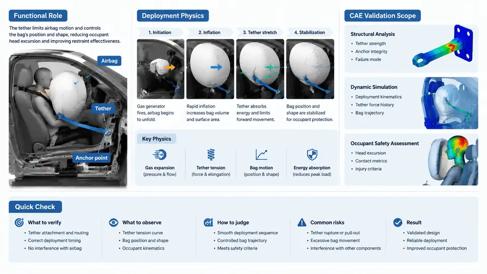
An airbag tether is a length of woven fabric—typically nylon 6.6 or polyester—sewn between two internal points of an airbag cushion. Its purpose is deceptively simple: constrain how far a portion of the cushion can travel during inflation. That single geometric constraint governs cushion shape, internal pressure distribution, occupant contact timing, and ultimately injury metrics. In modern restraint systems, tethers are not accessories; they are primary design variables. A 20 mm change in tether length can shift peak chest deflection by several millimeters in a frontal impact, which is often the difference between a passing and failing occupant test.
Functional Role of Tethers in the Restraint System
Tethers perform four distinct functions, and a single tether often serves more than one simultaneously.
- Shape control: A tether pulls the cushion into a non-spherical geometry, creating the flat or concave contact surface that distributes load across the occupant's chest rather than concentrating it at a single point.
- Depth limitation: By restricting cushion thickness, the tether prevents the bag from wrapping around the occupant's head or torso, which can cause neck loading or submarining.
- Pressure management: Tethers partition the cushion into chambers. Gas must flow between chambers through vent paths or fabric porosity, which slows the pressure rise in the occupant-facing region and reduces the "punch-out" effect during early deployment.
- Deployment trajectory: In side airbags and knee airbags, tethers guide the cushion along a specific path—for example, downward along the instrument panel or upward along the A-pillar—so the bag reaches the intended contact zone before the occupant moves into it.
Consider a typical driver frontal airbag. Without tethers, the cushion inflates as a roughly spherical volume with a diameter determined by gas volume and fabric stretch. With a single central tether of 120 mm length, the cushion becomes a flattened torus-like shape with a recessed center. The occupant's chest contacts the recessed region, which has lower internal pressure and greater compliance. The tether effectively converts a stiff, high-pressure bag into a softer, larger-area contact surface. This is why tether length, attachment location, and seam strength are specified on the airbag drawing with tolerances often tighter than ±3 mm.
Deployment Physics: What Happens in the First 30 Milliseconds
Airbag deployment is a gas dynamics problem coupled with fabric mechanics. The inflator releases gas at a mass flow rate that peaks within 5–15 ms and then decays. The cushion fabric stretches, seams load, and tethers tension. The tether's mechanical response is dominated by three factors: length, stiffness, and attachment point compliance.
During the initial inflation phase (0–10 ms), the cushion is not yet fully pressurized. The tether is slack or lightly loaded. As pressure rises, the tether tension increases according to the membrane equation for a constrained fabric panel:
T = P × A / (2 × sin θ)where T is tether tension, P is internal pressure, A is the projected area of the constrained panel, and θ is the angle between the tether and the fabric surface. A small θ (tether nearly parallel to the fabric) produces very high tension for a given pressure. This is why tether attachment points are reinforced with multiple rows of stitching and often a patch of heavier fabric.
The tether also affects the timing of occupant contact. In a 50 km/h frontal rigid barrier test, the occupant's chest begins to move forward at approximately 30–40 ms after impact. The airbag must be fully deployed and venting by that time. A tether that is too long allows the cushion to over-expand, delaying pressure buildup in the contact zone and potentially allowing the occupant to "bottom out" against the module. A tether that is too short restricts cushion volume, raising peak pressure and increasing chest deflection. The design window is narrow—often only 10–15 mm of tether length adjustment.
Example design window: For a mid-size sedan driver airbag with a 60 L cushion and a 200 kPa peak pressure target, a central tether length of 110–125 mm typically produces chest deflection between 25 and 32 mm in a 50 km/h frontal test. Lengths below 105 mm push deflection above 35 mm; lengths above 130 mm risk bottom-out and high neck loads.
CAE Validation Scope: What the Simulation Must Capture
CAE validation of tether systems is not a single simulation. It is a hierarchy of models, each answering a different question. The scope spans material characterization, component-level tests, subsystem simulations, and full-vehicle occupant safety analysis.
| Validation Level | Objective | Typical CAE Method | Key Output |
|---|---|---|---|
| Material coupon | Fabric stiffness, strain rate sensitivity, seam strength | Uniaxial tensile, shear frame, seam peel | Stress–strain curves, failure strain |
| Component (tether) | Tether tension vs. displacement, attachment strength | Explicit dynamics, shell elements, tied contacts | Force–displacement curve, peak tension |
| Subsystem (cushion) | Deployment shape, pressure history, chamber interaction | CPM or FPM with fluid–structure interaction | Pressure–time, cushion geometry at 30 ms |
| Full vehicle | Occupant injury metrics (HIC, chest deflection, neck force) | Hybrid III or THOR dummy, sled or full-scale FE | Injury criteria vs. targets |
The most common CAE approach for airbag deployment is the Corpuscular Particle Method (CPM) or Finite Pointset Method (FPM) for gas dynamics, coupled with a Lagrangian shell mesh for the fabric. Tethers are modeled as either 1D seatbelt elements or 2D shell strips. The choice matters: 1D elements capture axial tension well but cannot represent fabric wrinkling or bending stiffness. 2D shell tethers are more accurate but require finer mesh and careful contact definitions.
A critical validation step is the tether tension calibration. Experimental data from a static deployment test—where the cushion is inflated with compressed air while tether tension is measured using a load cell—provides the target curve. The CAE model is then tuned by adjusting fabric permeability, seam stiffness, and contact friction until the simulated tension matches the measured peak and rise time within 10–15%. Without this step, full-vehicle occupant results are unreliable because tether tension directly controls cushion shape and pressure distribution.
Common pitfall: Neglecting strain rate effects in the tether fabric. Nylon 6.6 can stiffen by 30–50% at strain rates above 100 s⁻¹, which are typical during deployment. Using quasi-static material properties in an explicit simulation underestimates tether tension and overestimates cushion expansion, leading to optimistic chest deflection predictions.
Visualizing the Tether–Cushion–Occupant Interaction
The following diagram illustrates the functional relationship between tether geometry, cushion shape, and occupant contact. It is a cross-sectional view of a driver airbag at approximately 30 ms after deployment, showing how a central tether creates a recessed contact surface and how tether tension varies with attachment angle.
The diagram shows the essential CAE validation target: the tether tension T must be high enough to maintain the recessed contact zone but low enough to avoid seam failure. The attachment angle θ is a design variable—reducing it increases tension, which can be beneficial for shape control but detrimental for seam durability. In CAE, this angle is extracted from the deformed mesh at peak pressure and compared against the design intent.
Scope of CAE Validation: What to Include and What to Exclude
A complete CAE validation scope for tether systems includes:
- Fabric material model calibration: Uniaxial and biaxial tensile tests at quasi-static and dynamic rates. The model must capture nonlinear stiffness, hysteresis, and failure strain.
- Seam and attachment modeling: Tied contacts or cohesive zone elements at tether-to-cushion interfaces. Seam strength is often the limiting factor, not fabric strength.
- Gas flow and pressure coupling: CPM or FPM particles with a defined inflator mass flow curve. The tether affects chamber volume, which in turn affects pressure.
- Contact and friction: Tether-to-fabric and fabric-to-occupant contact. Friction coefficients between nylon and nylon are typically 0.2–0.3, but can vary with surface finish and lubrication.
- Occupant positioning: The dummy model must be positioned according to the test setup (e.g., 50th percentile male, 25 mm out-of-position). Tether length affects the cushion's ability to reach the occupant before bottom-out.
What can be excluded from the initial validation scope? Detailed stitching geometry, individual yarn-level behavior, and thermal effects from the inflator. These are typically handled through safety factors or empirical adjustments. The goal is not to simulate every fiber but to predict occupant injury metrics within engineering accuracy—typically ±10% of physical test results for chest deflection and ±15% for neck force.
Practical guidance: Start CAE validation with a static deployment test (no occupant) to calibrate tether tension and cushion pressure. Once the pressure–time curve matches within 10%, add the occupant model. This two-step approach isolates tether-related errors from occupant positioning errors, saving significant iteration time.
In summary, tether systems are the primary geometric control element in modern airbag design. Their functional role spans shape, depth, pressure, and trajectory. Deployment physics couples gas dynamics with fabric mechanics, and the tether tension is the critical intermediate variable. CAE validation must therefore span material calibration, component-level tension prediction, subsystem deployment, and full-vehicle occupant response. The next chapter will detail the specific material models and test methods used to characterize tether fabrics and seams.