1. Airbag seam architecture and failure mod
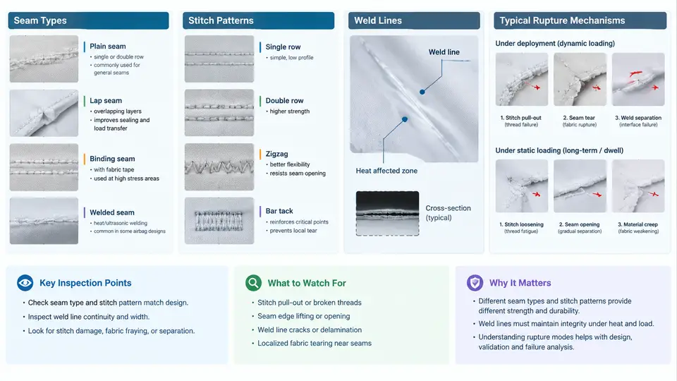
An airbag cushion is not a single homogeneous membrane. It is an assembly of woven fabric panels joined along engineered seams, and those seams are the weakest structural links in the entire restraint system. A driver-side airbag may contain 6–12 discrete seam segments; a side-curtain airbag can exceed 20 meters of total seam length. Because the cushion must inflate from a folded state to full deployment in 20–50 ms while withstanding internal pressures of 200–400 kPa, seam integrity governs whether the bag inflates as designed or ruptures catastrophically. This chapter establishes the architectural vocabulary and failure taxonomy that the remainder of the course builds upon.
Seam Types in Airbag Construction
Three joining technologies dominate production airbag cushions, and each produces a mechanically distinct seam.
Sewn seams are the most common. Two or more fabric layers are joined by a needle-and-thread system, typically using nylon 6.6 or bonded polyester thread sized 69–138 (Tex 70–140). The seam's strength depends on stitch density, thread tension, fabric weave, and the number of stitch rows. A single-row seam is rarely used in load-bearing regions; two-row and three-row configurations are standard for main panel joints.
Woven (one-piece-woven, OPW) seams eliminate thread entirely. The cushion is woven as a single fabric with interwoven junctions where warp and weft yarns cross between layers. OPW seams are common in side airbags and some passenger bags because they reduce labor, eliminate needle holes, and provide consistent permeability. However, the transition zone between single-layer and double-layer regions creates stress concentrations that behave differently from sewn seams.
Welded and bonded seams use heat, ultrasonic energy, or adhesive to fuse coated fabrics. Thermoplastic polyurethane (TPU) or silicone coatings on the fabric act as the bonding medium. Welded seams appear in specialized applications such as certain curtain airbags and inflatable seat belts, where the seam must remain gas-tight over long storage periods.
Stitch Patterns and Their Mechanical Signatures
Stitch type is defined by ISO 4915 and ASTM D6193. The patterns relevant to airbags are:
- Lockstitch (Type 301): Two threads interlock in the fabric. Strong, but the bobbin thread limits elongation. Used in low-stress panel joins.
- Chainstitch (Type 401): A single thread forms loops on the underside. Higher elongation than lockstitch, better for seams that must stretch during deployment. Common in main cushion seams.
- Zigzag and multi-step zigzag (Types 304, 308): The needle traverses laterally, allowing the seam to elongate without thread breakage. Multi-step zigzag distributes strain across multiple stitch legs and is preferred in high-strain regions near the inflator attachment.
Stitch density is specified in stitches per inch (SPI). Airbag seams typically run 6–10 SPI. Below 6 SPI, the fabric between stitches can pull out (seam grin-through). Above 12 SPI, the needle perforates the fabric excessively, creating a perforation line that acts as a tear initiator.
Weld Lines and Bonded Interfaces
Weld lines are continuous or intermittent fused zones. Their mechanical behavior differs fundamentally from sewn seams: there is no thread to redistribute load, so the bond strength is limited by the coating's cohesive strength and the fabric-to-coating adhesion. Weld lines are characterized by width (typically 3–8 mm), energy density (ultrasonic) or temperature/pressure/dwell time (thermal), and peel strength. A weld line that is too narrow concentrates stress; one that is too wide creates a stiff band that resists the fabric's natural compliance, causing adjacent fabric to fail first.
Typical Rupture Mechanisms
Seam failure under deployment and static loading follows recognizable patterns. The figure below maps the four dominant mechanisms to their locations and driving conditions.
Seam slippage occurs when the fabric yarns pull out from between stitch holes rather than the thread breaking. It is favored by low stitch density, high fabric crimp, and loading perpendicular to the seam. In deployment, the rapid pressure rise causes the fabric to "grin" through the seam, producing a gap that grows into a rupture. Static loading at 50 mm/min can reproduce this mechanism if the seam is loaded in shear.
Thread rupture is a tensile failure of the stitching thread itself. It dominates when the thread is weaker than the fabric, when the seam is loaded parallel to the stitch line, or when abrasion from adjacent fabric layers degrades the thread. Under deployment, strain rates of 100–1000 s⁻¹ reduce thread elongation at break, making rupture more likely than in quasi-static tests.
Needle-line tear is a fabric failure, not a thread failure. The needle perforations create a line of reduced cross-section. When the seam is loaded, the tear initiates at one perforation and propagates along the stitch row. This mechanism is sensitive to needle size, needle temperature (which can melt synthetic fabric), and SPI. It is often misdiagnosed as thread rupture because the visual result—an open seam—looks similar.
Weld delamination is unique to bonded seams. The coating separates from the fabric substrate, or the coating itself cohesively fails. It is driven by peel and shear stresses at the weld boundary. In deployment, the rapid inflation creates a peel front that can unzip a weld line in milliseconds if the bond strength is marginal.
Static vs. Deployment Loading: Why Both Matter
Static loading (tensile tests at 50–500 mm/min) reveals the seam's quasi-static strength and failure mode. Deployment loading (internal pressure ramp of 200–400 kPa in 20–50 ms) adds strain-rate sensitivity, inertial effects, and multi-axial stress states. A seam that passes static testing can still fail in deployment if its strain-rate sensitivity is unfavorable or if the stress concentration at seam terminations is not captured by uniaxial tests. Conversely, a seam that fails statically at low load may survive deployment if the load path in the inflated geometry avoids the weak region.
Design and Validation Implications
Three practical rules follow from this taxonomy. First, seam type and stitch pattern must be selected for the dominant loading mode: chainstitch or multi-step zigzag for high-strain deployment regions, lockstitch for low-strain panel joins. Second, seam terminations—where a seam ends or changes direction—are stress risers and should be reinforced with backstitching, bar tacks, or a gradual taper. Third, weld lines require process control on energy density and surface cleanliness; a 10% drop in ultrasonic energy can reduce peel strength by 30% or more.
The next chapter examines how these failure modes are quantified through standardized test methods and how seam efficiency is calculated from raw material properties.