1. Airbag module architecture
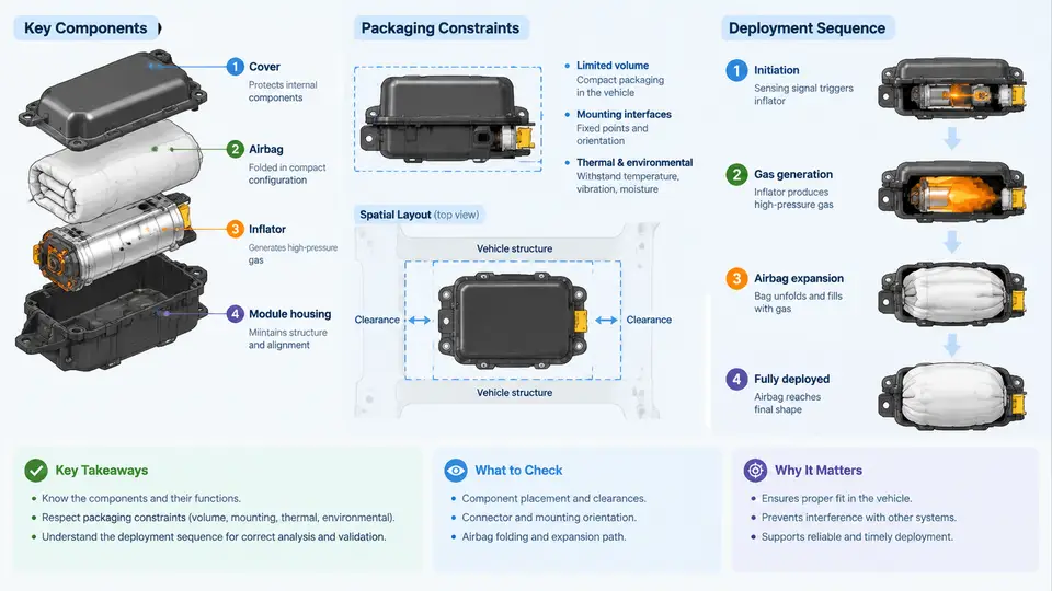
An airbag module is not a single part but a tightly integrated assembly whose geometry, materials, and timing must all be resolved before a single simulation run is meaningful. In packaging and deployment simulation, the module defines the boundary conditions: where the gas gener- ator sits, how the cushion is folded, which surfaces the cushion contacts first, and how the cover opens. Getting the architecture right at the start prevents the most common failure mode in CAE work — a model that converges numerically but represents a physical assembly that could never be built or deployed.
Core components of a driver-side module
A typical driver-side airbag module contains five functional groups. The inflator (gas generator) is a pyrotechnic or hybrid device that produces gas on command; its output is characterized by a mass flow rate curve and a gas temperature curve, both of which are direct simulation inputs. The cushion is a woven fabric bag, usually nylon 6.6, with a defined permeability and seam pattern. The retainer or housing holds the folded cushion and mounts the module to the steering wheel armature. The cover is the visible class-A surface; it carries a tear seam that must rupture predictably. Finally, the mounting and electrical interface includes the clock spring connector, mounting studs, and the wiring harness.
Each component contributes a distinct modeling requirement. The inflator becomes a boundary condition (a time-dependent mass flow and temperature source). The cushion becomes a shell or membrane mesh with orthotropic fabric properties. The cover becomes a fracture model with a defined tear-seam strength. The retainer becomes a rigid or deformable constraint. Confusing these roles — for example, modeling the inflator as a rigid body without a flow source — produces a simulation that inflates nothing.
Packaging constraints that drive the simulation
Packaging is where architecture meets geometry. The folded cushion must fit inside the retainer envelope, and that envelope is bounded by the steering wheel hub, the driver's hands, and the instrument panel or column covers. Three constraints dominate:
- Envelope volume: the folded cushion's bounding box must not exceed the retainer cavity. In practice, a driver-side cushion folds to roughly 120–180 mm in diameter and 60–90 mm in thickness, depending on bag volume (typically 60–70 L for a driver module).
- Tear-seam location: the cover's tear seam must align with the cushion's deployment path. If the seam is offset, the cushion can deploy asymmetrically or fail to open the cover.
- Clearance to adjacent surfaces: the module must not contact the steering wheel rim, horn contacts, or column shroud during deployment. A minimum clearance of 5–10 mm is a common design guideline, verified in simulation by tracking node-to-surface distances.
These constraints are not independent. Reducing envelope volume by folding more tightly increases the cushion's internal contact forces and can delay deployment. Increasing tear-seam strength prevents accidental opening but may cause the cover to fragment rather than split cleanly. The simulation must capture these trade-offs, which is why the folded geometry and the cover model are usually built together.
Deployment sequence and its simulation representation
Deployment proceeds in a fixed sequence that the simulation must reproduce step by step. The sequence begins when the ECU sends a firing signal, typically 10–30 ms after a crash pulse is detected. The inflator ignites, and gas begins to fill the cushion. The cushion first pressurizes the folded volume, then unfolds along its fold pattern, then contacts the cover, then ruptures the tear seam, and finally inflates to full volume. Full inflation for a driver module is typically reached 30–50 ms after firing.
In simulation, this sequence is represented as a time-dependent process. The inflator's mass flow curve drives the cushion's internal pressure. The cushion's fold pattern determines the initial contact and unfolding path. The cover's tear seam is modeled as a cohesive zone or a stress-based failure criterion. The simulation output — cushion pressure, cover opening time, and cushion trajectory — is compared against design targets.
Example simulation setup (illustrative values): A driver-side module with a 65 L cushion, inflator mass flow peaking at 2.5 kg/s at 15 ms, and a cover tear seam with a tensile strength of 8 MPa. The simulation runs for 80 ms with a time step of 0.5 ms. Key outputs: peak cushion pressure (target 250–350 kPa), cover opening time (target 20–30 ms), and cushion-to-rim clearance (minimum 5 mm).
Typical failure symptoms and their causes: if the cushion pressure rises too slowly, the inflator curve may be mis-specified or the cushion permeability too high. If the cover opens late, the tear seam strength may be too high or the cushion-to-cover contact may be poorly defined. If the cushion deploys asymmetrically, the fold pattern or the inflator orientation may be incorrect. Each symptom points to a specific architectural input, which is why the component list and the deployment sequence must be established before meshing begins.
Why architecture must precede meshing
The most expensive mistake in airbag simulation is starting the mesh before the architecture is fixed. If the inflator location changes, the mass flow boundary condition must be re-mapped. If the fold pattern changes, the initial cushion geometry must be rebuilt. If the cover tear seam moves, the contact definitions and failure criteria must be redefined. Each change cascades through the model. By establishing the component list, the packaging constraints, and the deployment sequence first, the simulation engineer can define a stable set of inputs and avoid rework.
A practical check before meshing: confirm that the folded cushion fits the retainer envelope, that the tear seam is within 5 mm of the cushion's initial contact zone, and that the inflator's mass flow curve is available as a time-series table. If any of these is missing, the simulation will produce numbers but not insight. The architecture is the contract between design intent and simulation fidelity.
Practical note: When receiving a new module design, request the inflator mass flow curve, the cushion fold drawing, the cover tear-seam specification, and the retainer envelope dimensions before opening the pre-processor. These four inputs define the simulation's boundary conditions and prevent the most common rework cycles.