1. Airbag inflator system architecture
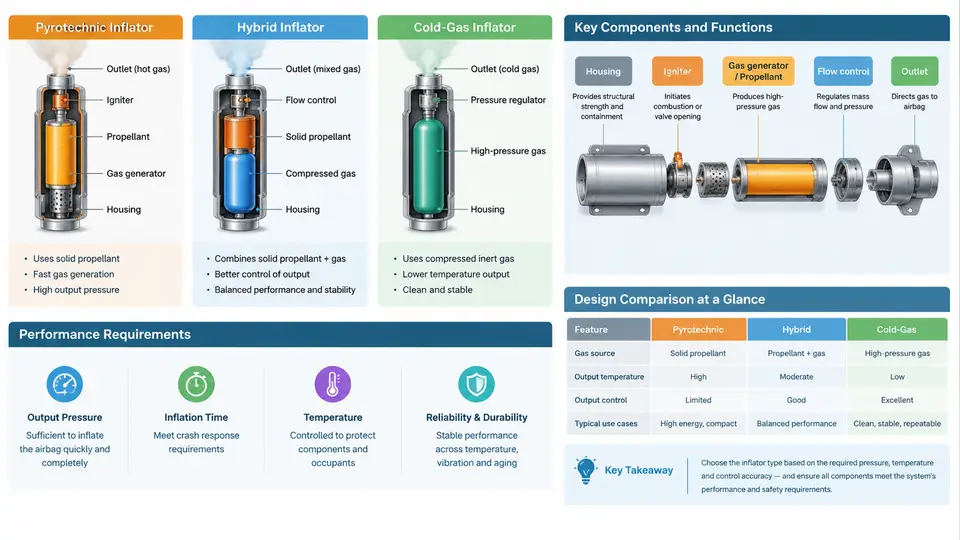
An airbag inflator is a controlled gas generator. Its job is deceptively simple to state and difficult to achieve: produce a specified mass of gas, at a specified temperature and pressure, within a tightly bounded time window, and do so reliably after years of dormancy across a wide temperature range. Everything in inflator modeling and gas flow simulation ultimately traces back to this architecture. Before writing a single conservation equation, you need to know which type of inflator you are modeling, what each internal component contributes, and which performance requirements constrain the design.
The Three Architectural Families
Production inflators fall into three families distinguished by how the working gas is stored and released.
Pyrotechnic (solid-propellant) inflators contain a solid gas generant — historically sodium azide-based, now largely guanidine nitrate or similar non-azide formulations — plus an initiator, a booster, a combustion chamber, a filter/coolant pack, and burst disc or exit ports. On receipt of a firing current, the initiator ignites the booster, which ignites the main propellant grain. Combustion generates gas at roughly 1500–2500 K, and the gas then passes through a filter pack that removes particulates and, critically, absorbs heat. The delivered gas temperature at the module exit is typically in the 500–900 K range for driver-side units. The propellant mass for a driver inflator is on the order of 40–120 g, producing 1.5–3.0 mol of gas.
Hybrid inflators combine a small pyrotechnic charge with a stored compressed gas, usually argon or helium-rich argon at 20–40 MPa in a steel or aluminum pressure vessel. The pyrotechnic charge does not supply the bulk gas; it supplies the energy to heat the stored gas and rupture the seal. Because the stored gas is already present, hybrid inflators deliver gas at lower peak temperature than pure pyrotechnic units and can be tuned by adjusting fill pressure and charge mass independently. This decoupling is the main architectural advantage: gas mass comes from the vessel, gas temperature from the charge.
Cold-gas inflators store gas only, with no propellant at all. A pyrotechnic or mechanical actuator opens a valve or ruptures a diaphragm, and the pressure differential drives the gas out. Cold-gas designs are common in side airbags, curtain airbags, and pedestrian-protection systems where slower, cooler inflation is acceptable or desirable. Their output temperature is essentially ambient plus whatever heating occurs during expansion, so downstream fabric and trim see far less thermal load.
Component Functions and the Gas Path
The figure below traces the gas path and the functional role of each component across the three architectures.
Performance Requirements That Drive the Design
Inflator performance is specified through a small set of measurable quantities, and each maps directly to a modeling parameter.
| Requirement | Typical Target | Modeling Parameter |
|---|---|---|
| Time to 90% fill (driver) | 25–40 ms | Mass flow rate ṁ(t), orifice area |
| Peak bag pressure | 50–80 kPa over ambient | Chamber pressure, vent area |
| Exit gas temperature | < 900 K (pyro), < 600 K (hybrid) | Energy balance, filter effectiveness |
| Particulate output | < 1 g per firing | Filter efficiency, burn completeness |
| Service life | 15+ years, −35 °C to +85 °C | Seal leakage, propellant aging |
| Firing current | 1.2–2.0 A, 2 ms pulse | Initiator bridgewire energy |
The temperature requirement is the one most often underestimated. A pyrotechnic inflator that delivers gas at 1200 K will scorch the bag fabric and can ignite trim materials. The filter/coolant pack is therefore not optional — it is a primary performance component, and its thermal mass and heat-transfer area appear directly in the chamber energy equation as a sink term.
From Architecture to Simulation Input
Consider a driver-side pyrotechnic inflator you intend to model. The minimum input set is:
- Propellant mass
m_pand burn-rate coefficientsa,ninr = a·P^n - Chamber free volume
V_cand its variation as propellant is consumed - Filter thermal mass
m_f·c_fand effective heat-transfer coefficienth·A - Burst disc opening pressure
P_burstand exit port areaA_exit - Discharge coefficient
C_dfor the exit path (typically 0.7–0.9)
A representative teaching example uses m_p = 65 g, a = 0.008 m/(s·Pa^n), n = 0.45, V_c = 60 cm³, P_burst = 12 MPa, and A_exit = 900 mm². Running a lumped chamber model with these values produces a chamber pressure that peaks near 18 MPa at roughly 8 ms and a mass flow rate that rises to about 1.8 kg/s before decaying as the propellant is consumed. These are illustrative values for a generic driver inflator, not measured data from a specific unit.
Common Failure Modes and Their Signatures
When an inflator model or a physical unit misbehaves, the symptom usually points to a specific component. A chamber pressure that rises too slowly suggests a burn-rate coefficient that is too low or an initiator delay that was not modeled. A pressure spike followed by an immediate collapse indicates the burst disc opened early or the exit area is oversized. Gas that arrives too hot points to an undersized filter thermal mass. In hybrid units, a fill curve that plateaus below target usually means the stored-gas mass was underestimated or the vessel temperature was initialized incorrectly.
These signatures matter because they tell you which parameter to revisit. Architecture determines the model structure; the performance requirements determine the target values; the failure signatures tell you where the model and reality diverge. With this foundation, the next step is to write the governing equations for the chamber and the gas path.