3. Material modeling for airbag fabrics
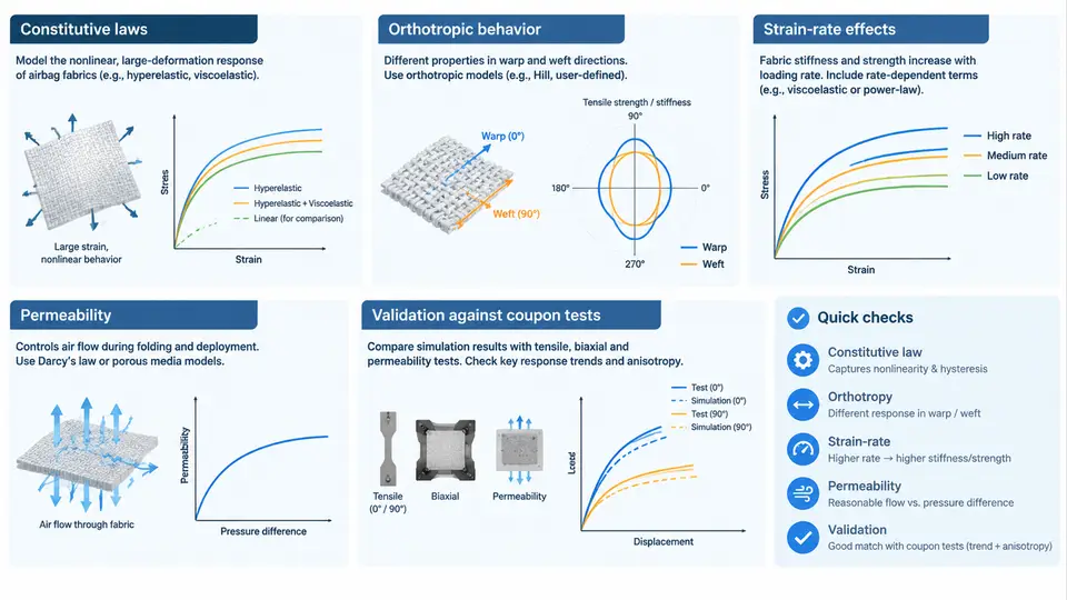
An airbag is not a rigid pressure vessel. It is a woven, coated, highly compliant membrane that inflates in tens of milliseconds, wrinkles, contacts occupants, and vents gas through its own porosity. If the fabric constitutive model is wrong, the deployment kinematics will be wrong regardless of how refined the gas model or contact definition is. This section covers the material laws used for airbag fabrics, how orthotropy and strain-rate sensitivity are represented, how permeability is coupled to the structural response, and how all of this is validated against coupon tests before it is trusted in a full deployment simulation.
Why Fabric Is Not an Isotropic Shell
Airbag fabric is typically a plain-weave nylon 6.6 (or polyester) with a silicone or polyurethane coating. The weave architecture produces two distinct in-plane directions: the warp (machine direction, along the roll) and the weft (fill direction, across the roll). Yarns are much stiffer along their axis than the fabric is in shear, and the coating dominates through-thickness and permeability behavior. The practical consequence is that a single Young's modulus and Poisson's ratio cannot describe the material.
Two modeling families are used in production CAE:
- Orthotropic elastic / hyperelastic membrane or shell — fast, stable, and adequate when the fabric remains taut and the loading is dominated by biaxial tension. Suitable for early design iterations and for regions that never go slack.
- Anisotropic fabric material with directional damage and slack behavior — required when folding-induced wrinkles, yarn reorientation, or local buckling matter. LS-DYNA's
*MAT_FABRICand comparable models in PAM-CRASH and Abaqus/Explicit fall into this class.
The choice is not academic. A membrane model that cannot go slack will artificially stiffen a folded airbag and delay the early inflation phase, which directly shifts occupant contact timing.
Constitutive Laws and Orthotropic Behavior
For a woven fabric modeled as a shell, the in-plane stress–strain relation in the material coordinate system (1 = warp, 2 = weft) is written as:
[σ11]   [ E1/(1-ν12ν21)    ν21E1/(1-ν12ν21)      0      ] [ε11]
[σ22] = [ ν12E2/(1-ν12ν21)  E2/(1-ν12ν21)         0      ] [ε22]
[σ12]   [        0                  0          G12     ] [γ12]
Typical coupon-derived values for a 470 dtex silicone-coated nylon 6.6 at quasi-static rates are E1 ≈ 1.2–2.5 GPa, E2 ≈ 0.9–1.8 GPa, G12 ≈ 20–60 MPa, and ν12 ≈ 0.15–0.25. Note that G12 is one to two orders of magnitude lower than the axial moduli — this is the signature of a woven fabric and the reason shear locking and hourglass control need attention in explicit simulations.
Because the fabric is thin and cannot carry compression, the model must include a slack or tension-only condition: once a yarn direction goes into compression, its stiffness drops to a small residual value (often 1–5% of the tensile modulus) rather than going negative. This is what allows the folded bag to unfold naturally.
Strain-Rate Effects
Airbag deployment subjects the fabric to strain rates from roughly 10 s⁻¹ in the early unfolding phase up to 500–1500 s⁻¹ in the fully inflated, taut membrane. Nylon 6.6 is viscoelastic: both the axial modulus and the failure strain increase with rate, while the failure strain in the weft direction typically increases more than in the warp.
Two practical approaches are common:
- Rate-dependent modulus via a tabulated curve. Define E1(ε̇) and E2(ε̇) from split-Hopkinson or high-rate tensile tests and let the solver interpolate. This is the most direct route and is supported by most explicit codes.
- Viscoelastic / viscoplastic overlay. A Prony-series shear relaxation combined with a rate-independent elastic backbone. More physical, but requires more calibration data and can be numerically stiff.
If rate data are unavailable, a defensible engineering fallback is to use the high-rate modulus for the inflation phase and the quasi-static modulus for the post-contact phase, switching at a defined internal pressure threshold. This is an approximation and must be documented as such in the model report.
Permeability and Its Coupling to Structure
Permeability is the gas leakage through the fabric itself, distinct from vent holes and seam leakage. It is driven by the pressure differential across the membrane and is strongly dependent on the coating integrity and on the local strain state — a stretched fabric opens its weave and leaks more.
In LS-DYNA the standard approach is *MAT_FABRIC with the PERM flag, which activates a porous leakage model. The leakage velocity is computed from a Fabry or Ergun-type relation:
v_leak = C1 * ΔP^C2where ΔP is the pressure difference across the shell and C1, C2 are calibrated from a permeability coupon test (typically a fixed-pressure decay test on a clamped fabric sample). For a coated nylon at 50 kPa differential, a representative C1 is on the order of 1e-4 to 1e-3 (units consistent with the solver's unit system) with C2 ≈ 0.5–0.8. These values are illustrative and must be replaced with measured data for any real program.
The coupling matters because leakage reduces the internal pressure that drives the membrane stress, which in turn reduces the strain that opens the weave. This is a two-way feedback loop, and it is one of the main reasons a purely structural fabric model without permeability will over-predict bag stiffness and under-predict inflation time.
Validation Against Coupon Tests
A fabric model is only as good as the coupon correlation behind it. The validation sequence should proceed from the simplest loading case to the most complex, and each level must be closed before moving up.
| Level | Test | Primary output | Acceptance criterion (example) |
|---|---|---|---|
| 1 | Uniaxial tensile, warp and weft, quasi-static | E1, E2, failure strain | Modulus within ±10% of measured; failure strain within ±15% |
| 2 | Biaxial cruciform, 1:1 and 2:1 ratios | Interaction of warp/weft stiffness | Predicted stress ratio within ±12% at matched strain |
| 3 | Picture-frame shear | G12 and shear locking onset | Shear angle at lock-up within ±2° |
| 4 | High-rate tensile (10–1000 s⁻¹) | Rate-dependent modulus | Trend and magnitude within ±20% across rate range |
| 5 | Pressure-decay permeability | C1, C2 | Decay curve within ±15% over 0–80 kPa |
Only after levels 1–5 are closed should the model be used in a full bag deployment. At that point the bag-level correlation (internal pressure history, bag shape at 30 ms, occupant contact force) becomes the final acceptance gate. If bag-level results diverge while coupon-level results are good, the problem is usually not the material law but the folding pattern, the gas inflow model, or the contact definition — a useful diagnostic separation that coupon validation provides.
Common Failure Symptoms and Troubleshooting
- Bag inflates too slowly in simulation. Check whether the slack stiffness is too high or the permeability C1 is too large. A fabric that never goes slack will resist unfolding.
- Excessive hourglassing in the fabric shell. Usually caused by G12 being set too low without adequate hourglass control, or by a mesh that is too coarse relative to the wrinkle wavelength. Refine to at least 5–8 mm element size in the fold regions.
- Peak internal pressure over-predicted. Permeability is likely inactive or under-calibrated. Verify that the
PERMflag is set and that C1/C2 match the coupon decay test. - Failure strain not reached in simulation but observed in test. The rate-dependent failure strain may be missing; quasi-static failure strain is typically 15–25% lower than high-rate values.
The material model is the foundation of every downstream result in this course. Once the coupon-level correlation is closed and the rate and permeability behavior are represented, the folding and deployment simulations in the following sections can be interpreted with confidence rather than treated as qualitative animations.