3. Material characterization for airbag fab
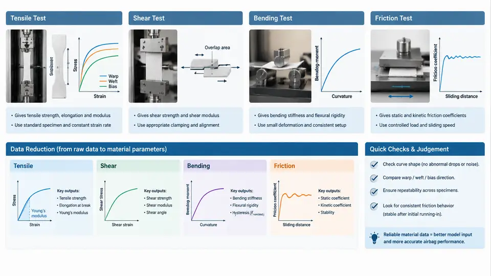
Airbag fabric is a highly anisotropic, rate-sensitive, coated or uncoated woven textile. Before any constitutive model can be calibrated, the four dominant deformation and interaction mechanisms must be measured independently: in-plane tensile response of the yarn system, in-plane shear response of the weave architecture, out-of-plane bending stiffness, and the friction that governs yarn-to-yarn and fabric-to-occupant sliding. Each mechanism maps to a distinct test method and a distinct data-reduction path. This section walks through the standard methods, the raw signals they produce, and how those signals become model-ready curves.
Tensile Characterization
Uniaxial and biaxial tensile tests are the primary source of warp and weft stiffness. For uniaxial testing, specimens are cut as strips (typically 50 mm wide, 200 mm gauge length) with yarns aligned to the loading axis. Because woven fabric crimps straighten before yarns extend, the initial response is very compliant; the curve then stiffens as yarns become taut. This "crimp region" is the most important part of the curve for airbag deployment, where strains can exceed 20%.
Biaxial testing is essential because airbag fabric is almost never loaded in one direction alone. A cruciform specimen is clamped on four arms and loaded independently in warp and weft. The key data-reduction step is separating the measured crosshead force into yarn-direction stress using the actual specimen cross-section, then plotting stress–strain for each axis at fixed load ratios (e.g., 1:1, 2:1, 1:2). The result is a family of curves that reveals how weft tension softens warp response — a direct consequence of crimp interchange.
Shear Characterization
In-plane shear controls the fabric's ability to conform to curved surfaces and its resistance to wrinkling. The picture-frame (trellis) test is the standard method: a square specimen is clamped along four edges and the frame is pulled diagonally, imposing pure shear on the central region. The measured force and frame angle give shear force per unit length versus shear angle.
Two regimes appear. At small shear angles (0–5°), the fabric is compliant as yarns rotate and crimp exchange. Beyond a locking angle (typically 15–30° for airbag fabrics), adjacent yarns jam, and shear stiffness rises sharply. The locking angle is a critical input for forming and deployment simulations because it marks the onset of wrinkling. Data reduction converts frame force F and frame displacement d into shear angle γ and shear force per unit length Fs using the frame geometry; the shear modulus G is then the local slope of the Fs–γ curve.
Bending Characterization
Bending stiffness of airbag fabric is low but not negligible — it influences fold patterns, packability, and the initial unfolding sequence. The cantilever (ASTM D1388) and Kawabata pure bending tests are both used. In the cantilever test, a strip is pushed over an edge and the overhang length L is measured; bending stiffness B is computed from the fabric weight per unit area w and L:
B = w * (L / 2)^3 [N·mm²/mm width]For coated fabrics, the coating adds a thin, stiffer layer, so bending stiffness is rate- and curvature-dependent. The Kawabata KES-FB2 test applies pure curvature and measures the moment–curvature hysteresis loop. The loop area quantifies energy dissipation, which is important for damping during deployment. Data reduction extracts the elastic bending modulus from the initial slope and the hysteresis width from the loop.
Friction Characterization
Friction appears at two interfaces: yarn-to-yarn within the weave and fabric-to-fabric or fabric-to-occupant at contact surfaces. The yarn pull-out test measures the force required to pull a single yarn from a woven strip; the peak force and the plateau force give static and kinetic friction contributions. For fabric-to-fabric sliding, a sled test (ASTM D1894 style) or a capstan test is used. The coefficient of friction μ is derived from the ratio of friction force to normal load, but for textiles it is strongly velocity- and pressure-dependent.
Data reduction should report μ as a function of sliding velocity and normal pressure, not a single scalar. A practical form is a power-law or exponential fit:
μ(v, p) = μ0 * (v / v0)^a * (p / p0)^bwhere μ0 is a reference coefficient, v0 and p0 are reference velocity and pressure, and a, b are fitted exponents. This captures the observed behavior that airbag fabric becomes more slippery at high sliding speeds, which reduces occupant loading but also affects bag unfolding.
From Raw Data to Model-Ready Parameters
The four test families produce different raw signals, but the reduction workflow shares a common logic: isolate the mechanism, convert engineering measurements to intrinsic quantities, and fit a parametric form that can be evaluated at arbitrary strain, rate, and pressure. A practical checklist for the reduction stage is:
- Tensile: Report stress–strain curves at each biaxial load ratio; extract tangent moduli at 5%, 10%, and 20% strain. Verify that the crimp-removal region is not clipped by the test start.
- Shear: Convert frame force to shear force per unit length; identify the locking angle as the knee in the curve; fit G before and after locking.
- Bending: Compute B from overhang length or from the initial slope of the moment–curvature loop; record hysteresis width as a damping parameter.
- Friction: Fit μ(v, p) over at least three velocities and three pressures; report the fit exponents and the reference values.
Once these parameters are extracted, they are assembled into a single material card. The tensile data define the orthotropic elastic or hyperelastic response; the shear data define the locking behavior; the bending data define the out-of-plane resistance; and the friction data define the contact interface. Validation then proceeds by comparing a full-scale airbag deployment simulation against instrumented drop-tower or sled tests, adjusting only the parameters whose test data had the largest uncertainty. This separation of mechanisms is what makes the characterization reproducible and the model defensible.