1. Airbag system architecture and deploymen
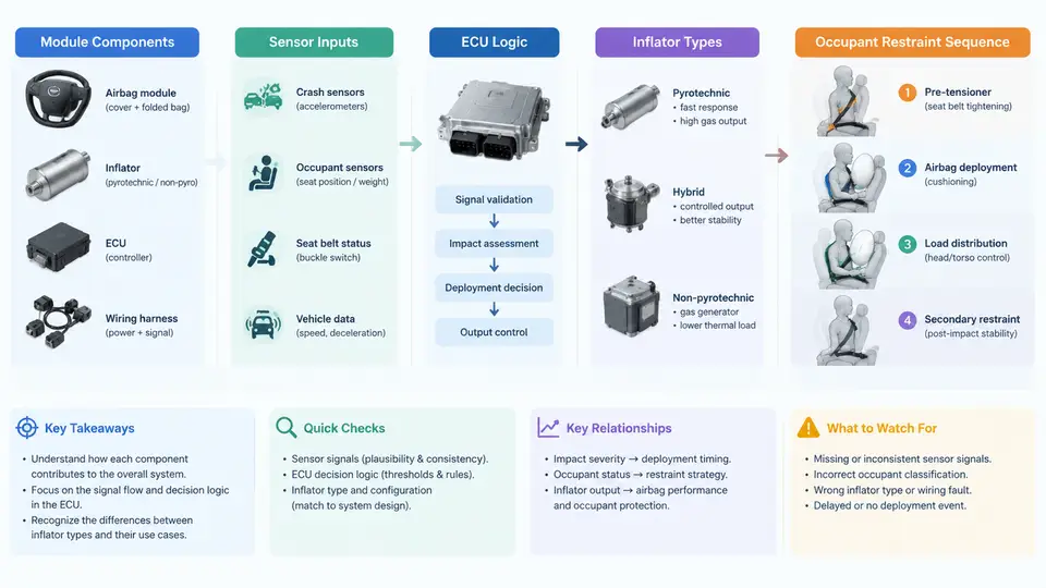
An airbag system is not a single device but a distributed, time-critical restraint subsystem. Its purpose is to place a cushioning volume between an occupant and a hard interior surface within a window of roughly 30–60 ms after a crash is detected. Understanding robustness and optimization begins with a precise mental model of the architecture: what components exist, how signals travel, how the ECU decides, how the inflator produces gas, and how the restraint sequence unfolds in time. This chapter builds that model from the module outward to the full deployment chain.
Module Components and Physical Layout
A driver frontal airbag module typically contains the folded cushion, the inflator, a reaction can or housing, a retainer ring, and a clock spring interface for the horn and driver-side circuits. Passenger modules add a chute or door assembly that tears along a molded seam. Side modules (seat-mounted or roof-rail) use smaller cushions and tubular or hybrid inflators. Each module is a sealed assembly; the cushion is folded in a controlled pattern so that it unfolds predictably rather than tangling.
Key electrical interfaces are the squib (initiator) connector, a shorting bar that prevents accidental firing during service, and a two-wire loop that the ECU monitors for continuity and resistance. A typical squib loop is specified around 2 Ω; the ECU flags a fault if measured resistance leaves a narrow window, for example 1.5–3.0 Ω. This diagnostic behavior is central to robustness because a degraded connector can disable a module without any crash event.
Sensor Inputs
Deployment decisions rely on several sensor classes:
- Frontal accelerometers mounted in the ECU or in the front crush zone, measuring longitudinal deceleration.
- Side pressure or acceleration sensors in doors or B-pillars, detecting lateral intrusion.
- Occupant sensors such as seat weight, seat position, and belt buckle status, used for suppression or dual-stage selection.
- Rollover and yaw sensors for curtain and side deployments.
Each sensor reports to the ECU over a dedicated bus or discrete line. The ECU continuously performs plausibility checks; a single out-of-range sensor can trigger a diagnostic trouble code (DTC) and, depending on severity, disable the affected function.
ECU Logic and the Deployment Decision
The airbag ECU is a safety microcontroller with redundant power, watchdog monitoring, and a crash algorithm running at a fixed sample rate, commonly 1–2 kHz. The algorithm integrates and filters acceleration to compute a velocity change (Δv) and compares it against a calibrated threshold that varies with crash severity and time. A simplified decision rule is:
if (delta_v(t) >= threshold(t)) and (crash_direction == FRONTAL):
    fire_stage_1 = True
    if (delta_v(t) >= threshold_stage2(t)):
        fire_stage_2 = True
The threshold curve is calibrated so that deployment occurs for a 50th-percentile male in a 50 km/h barrier impact but not for a low-speed parking bump. Robustness means this decision remains correct across temperature, voltage, and manufacturing variation. The ECU also manages the firing order and timing between stages and between modules.
Inflator Types
Three inflator families dominate:
| Type | Principle | Typical Use |
|---|---|---|
| Pyrotechnic | Solid propellant burns to produce gas | Driver frontal |
| Hybrid | Pyrotechnic heater pressurizes stored gas | Passenger, side |
| Stored gas | Compressed gas released by a valve | Some side/curtain |
Dual-stage inflators contain two independent squibs and propellant charges. The ECU can fire one or both, or stagger them, to match output to crash severity and occupant size. This is the primary actuator-level lever for optimization.
The Occupant Restraint Sequence
Deployment is a timed sequence, not a single event. In a typical frontal crash:
- Crash occurs; acceleration rises.
- ECU detects and validates the event (roughly 10–20 ms).
- Squib fires; inflator begins generating gas (1–3 ms).
- Cushion unfolds and pressurizes (20–40 ms).
- Occupant contacts the cushion as it vents through fabric or a vent hole.
- Belt pretensioner and load limiter manage occupant kinematics in parallel.
The belt system and airbag are co-designed. A pretensioner removes slack in 10–15 ms, and a load limiter controls belt force so the occupant decelerates with the cushion rather than bouncing off it. If the airbag fires too early, the occupant meets a deflating cushion; too late, the occupant has already moved forward. This timing sensitivity is why the deployment chain must be analyzed as a whole.
Practical Example: Verifying the Deployment Chain
Consider a bench validation of a driver frontal module. The input is a calibrated deceleration pulse representing a 50 km/h frontal barrier impact, applied to the ECU through a hardware-in-the-loop (HIL) rig. The ECU is powered at 13.5 V and soaked at 25 °C. The expected observable outputs are: a stage-1 squib command within 15–20 ms, a stage-2 command only if the pulse exceeds the severity threshold, and a cushion pressure rise reaching a target peak within 40 ms.
Typical failure symptoms and their causes:
- No squib command: check squib loop resistance; an open circuit or shorting bar left engaged will suppress firing.
- Late deployment: verify sensor mounting torque and ECU calibration; a loose sensor shifts the acceleration signal.
- Only stage 1 fires: confirm the stage-2 threshold and pulse severity; this may be correct behavior for a lower-severity input.
- DTC present: read the fault code; a persistent loop fault usually indicates connector or wiring degradation.
Why This Architecture Matters for Robustness
Every link in the chain introduces variability: sensor tolerance, ECU clock drift, squib resistance, propellant burn rate, cushion fabric permeability, and ambient temperature. Robust design means the system still meets its restraint targets when these variables stack unfavorably. The next chapters will quantify these effects and show how to optimize thresholds, inflator output, and cushion venting so that the deployment chain remains effective across the full operating envelope.