3. Airbag system architecture
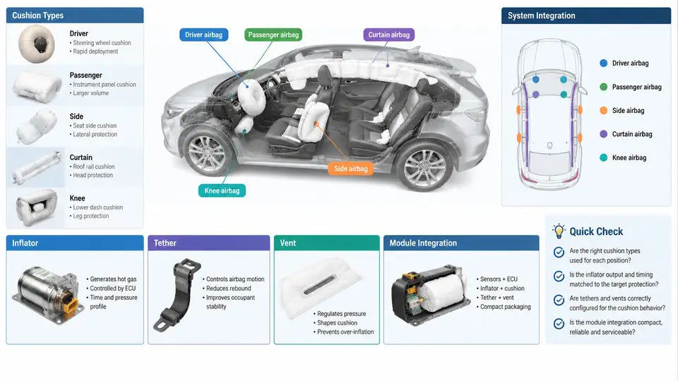
An airbag system is not a single product but a family of restraint modules, each engineered around the geometry of the occupant it protects and the direction of the impact it mitigates. In CAE terms, the architecture of a module determines almost everything downstream: how the cushion is modeled, which inflator curve drives the simulation, where tethers and vents are placed, and how the module is packaged into the vehicle. This chapter builds a working mental model of the five mainstream airbag families — driver, passenger, side, curtain, and knee — and the four architectural elements they share: cushion, inflator, tether, and vent.
Cushion Types and Their Design Intent
The cushion is the energy-absorbing membrane. Its shape is dictated by the occupant's position and the structure it must react against. A driver frontal airbag is a toroidal (donut-shaped) cushion mounted in the steering wheel hub. It deploys rearward toward the driver's chest and head, and its central recess accommodates the steering column. A passenger frontal airbag is a much larger, asymmetric cushion that deploys from the instrument panel top, filling the space between the dashboard and the passenger's torso and head. Because the passenger sits farther from the module, the cushion must be deeper and its deployment trajectory must be tuned to avoid striking a child or an out-of-position occupant.
Side airbags (thorax and thorax-pelvis) deploy from the seat back or door trim, expanding laterally to protect the torso and pelvis. Curtain airbags deploy downward from the roof rail, covering the side windows to protect the head. Knee airbags deploy from the lower instrument panel or steering column shroud, loading the knee and thigh to control lower-body kinematics and reduce femur and pelvis injury risk.
Each cushion type has a distinct CAE modeling implication. Driver and passenger cushions are typically modeled as a folded membrane with a defined deployment trajectory; side and curtain cushions require careful treatment of the seat and roof-rail interfaces; knee cushions are relatively small and stiff, and their interaction with the knee bolster and lower IP is critical.
Inflators: The Energy Source
The inflator determines the mass flow rate and gas temperature that fill the cushion. Three architectures dominate:
- Pyrotechnic inflators burn a solid propellant to generate gas. They are compact and fast, making them common in driver and side modules.
- Hybrid inflators combine a pyrotechnic charge with stored compressed gas. They offer a more controllable pressure-time curve and are widely used in passenger modules.
- Cold-gas inflators release stored gas without combustion, producing cooler gas and lower particulate output. They are used in some side and curtain applications.
For CAE, the inflator is represented by a mass flow rate curve (often called a tank curve or inflator curve) that specifies gas mass flow versus time, plus a gas temperature. This curve is the single most important input to the cushion deployment simulation. A typical driver inflator might reach peak mass flow within 10–20 ms and deliver 60–120 g of gas; a passenger inflator may deliver 200–400 g over 30–50 ms. These values are illustrative and must be replaced with the actual inflator supplier data for any real project.
Tethers and Vents: Shaping the Cushion
Tethers are internal fabric straps that constrain the cushion's inflated shape. They prevent over-expansion, control the cushion's depth, and keep the cushion from wrapping around the occupant's head. In CAE, tethers are modeled as membrane elements with defined lengths and attachment points. A common driver cushion uses a horizontal tether to limit rearward travel and a vertical tether to control the cushion's height.
Vents are openings that allow gas to escape, controlling the cushion's internal pressure and its interaction with the occupant. There are two main types: fabric vents (sewn or cut openings in the cushion) and active vents (pressure-relief valves that open at a threshold pressure). Vent size and location directly affect the cushion's pressure-time history and the occupant's ride-down. In simulation, vents are modeled as orifice flow boundaries with a discharge coefficient.
Module Integration Across Vehicle Zones
Module integration is where architecture meets packaging. The driver module is integrated into the steering wheel hub, with the inflator mounted on the wheel's central axis. The passenger module is integrated into the instrument panel, often with a chute or door that opens along a tear seam. Side modules are integrated into the seat frame or door trim, and curtain modules are packaged along the roof rail with a trim cover that deploys downward. Knee modules are integrated into the lower IP or steering column shroud.
Each integration point introduces constraints: the steering wheel's rotation, the IP's structural stiffness, the seat's adjustment range, and the roof rail's headliner clearance. In CAE, these are represented as boundary conditions and contact definitions. A common failure mode is cushion interference — the cushion strikes a trim piece or the steering wheel rim during deployment, causing it to tear or deploy off-axis. This is typically diagnosed by examining the cushion's deployment trajectory and contact forces in the simulation.
Practical CAE Workflow for Module Architecture
When building a module model, the first step is to define the inflator curve from supplier data. This curve is applied as a mass flow boundary condition at the inflator outlet. Next, the cushion geometry is created from the folded CAD model, and the tether and vent definitions are added. The cushion is then meshed with membrane elements, and the module is positioned in the vehicle environment.
A typical driver-side simulation might use a 50 ms run time with a 0.5 ms time step. The inflator curve might peak at 80 g/ms at 12 ms and decay to zero by 35 ms. The cushion pressure should rise to approximately 1.5–2.5 bar (gauge) within 20 ms and then decay as the occupant loads the cushion and gas escapes through the vents. If the pressure rises too slowly, the cushion may not be fully deployed when the occupant contacts it; if it rises too quickly, the cushion may be overly stiff and cause high chest accelerations.
Common troubleshooting scenarios include:
- Cushion under-deployment: Check the inflator curve scaling and the vent area. An oversized vent will bleed gas too quickly.
- Cushion over-expansion: Check tether lengths. A tether that is too long will not constrain the cushion, leading to excessive depth and potential interference with the steering wheel or IP.
- Off-axis deployment: Check the module mounting orientation and the cushion's initial fold pattern. A misaligned fold can cause the cushion to deploy sideways.
- High occupant loads: Check the vent timing and the cushion pressure profile. A delayed vent opening can cause a pressure spike at the moment of occupant contact.
Integration Constraints and Cross-Zone Interactions
Module integration is not independent across zones. A passenger airbag's deployment can interact with the windshield and the IP's structural response. A curtain airbag's deployment can be affected by the headliner's stiffness and the presence of a sunroof. A side airbag's deployment can be constrained by the seat's foam and the door trim's geometry. In CAE, these interactions are captured through contact definitions and multi-body coupling. For example, a curtain airbag model may include contact with the headliner, the seat, and the occupant's head, while a side airbag model may include contact with the seat frame and the door trim.
The key architectural decision is the deployment path: the cushion must be free to expand without obstruction. In the driver module, the steering wheel rim and spokes must not block the cushion. In the passenger module, the IP's tear seam must open cleanly. In the curtain module, the roof rail trim must release without fragmenting. These are validated through deployment trajectory analysis and, where possible, high-speed video correlation.
Summary
Airbag system architecture is a study in constrained energy management. The cushion type defines the protection zone; the inflator defines the energy input; the tethers and vents define the cushion's shape and pressure response; and the module integration defines the physical envelope and deployment path. In CAE, these elements are represented by a small set of inputs — the inflator mass flow curve, tether lengths, vent areas, and boundary conditions — that together determine the occupant's ride-down. Mastering this architecture is the foundation for every subsequent simulation task in this course.