1. Airbag cushion design and occupant prote
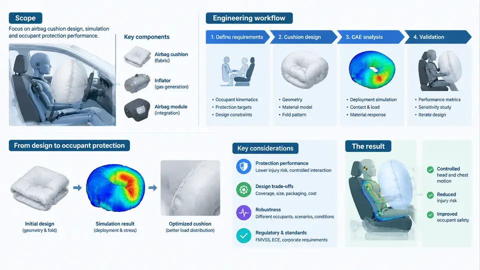
An airbag is not a bag. It is a precisely tuned energy-management device whose performance window is measured in milliseconds and whose design space is constrained by the occupant, the seat, the restraint system, the steering wheel or instrument panel geometry, and the vehicle structure itself. Airbag cushion design is the discipline of shaping how that device inflates, where it deploys, how it contacts the occupant, and how it dissipates energy. Occupant protection CAE is the numerical practice that predicts those events before a single prototype is built. This course treats the two as one integrated engineering activity, because in modern vehicle safety development they are inseparable.
What This Course Covers
The course spans the full technical chain from restraint system requirements to validated cushion performance. Its scope includes:
- Cushion architecture and geometry — driver, passenger, side, curtain, knee, and far-side airbags; single-chamber and multi-chamber constructions; tethering, seams, vents, and internal baffles.
- Inflator and gas dynamics — pyrotechnic, hybrid, and cold-gas inflators; mass flow rate, gas temperature, and pressure–time characteristics delivered into the cushion.
- Occupant protection CAE methods — explicit finite element analysis (FEA) with LS-DYNA or equivalent solvers, coupled with rigid-body or deformable occupant models such as Hybrid III 50th percentile male, 5th percentile female, and THOR.
- Injury criteria and targets — HIC15, HIC36, chest deflection, chest acceleration (3 ms clip), neck Nij, femur load, and the regulatory and consumer-rating thresholds that govern them (FMVSS 208, ECE R94/R95, Euro NCAP, C-NCAP).
- Validation and correlation — sled tests, static deployment tests, and the correlation metrics that decide whether a CAE model is trustworthy.
The course deliberately avoids treating CAE as a post-design verification step. Instead, it presents CAE as the primary design instrument: the model is built early, iterated often, and used to make decisions about vent size, tether length, inflator output, and module position long before hardware exists.
The Engineering Workflow
A typical airbag cushion development program follows a staged workflow. The stages are not rigid, but the logic is: define the protection target, build the model, tune the cushion, correlate against test, and release.
Stage 1 — Requirements and target setting. The restraint system team translates regulatory and consumer-rating requirements into occupant response targets. For a driver frontal airbag in a 56 km/h full-frontal rigid barrier test, a representative target set might be: HIC15 ≤ 500, chest deflection ≤ 45 mm, chest 3 ms clip ≤ 60 g, and femur load ≤ 6 kN. These are example targets, not universal values; they depend on the vehicle, the market, and the rating year.
Stage 2 — Model assembly. The CAE engineer builds a sled or full-vehicle model containing the occupant, seat, restraint belts, steering column or instrument panel, and the airbag module. The airbag itself is represented as a folded membrane mesh with a defined reference geometry, a fabric material model (typically a orthotropic membrane with Young's modulus around 2–4 GPa for nylon 6.6), and a gas inflow definition.
Stage 3 — Cushion tuning. This is the core design loop. The engineer adjusts vent hole diameter, tether length, chamber volume, and inflator mass flow to shape the cushion pressure–time curve and the occupant contact force. A larger vent reduces peak pressure but may allow the occupant to bottom out; a longer tether changes the cushion's deployed shape and contact area.
Stage 4 — Correlation. The model is compared against sled or static deployment test data. Correlation metrics include peak occupant acceleration, timing of peak, cushion pressure at specific instants, and deployment kinematics. A model is typically considered correlated when peak values are within 10–15% and timing within 5–10 ms.
Stage 5 — Design release and documentation. The correlated model supports the final cushion specification: fabric type, panel dimensions, seam pattern, vent size, tether geometry, and inflator part number.
Where CAE Sits in Vehicle Safety Development
Vehicle safety development runs on a parallel track of physical testing and numerical simulation. Physical tests are expensive and slow: a single sled test can cost tens of thousands of dollars and consume weeks of schedule. CAE is cheap and fast by comparison, which is why it carries the burden of design exploration. The relationship is not competitive but complementary: CAE narrows the design space, and physical tests validate the final candidate.
In a typical program, CAE supports the following decisions:
| Decision | CAE Contribution | Physical Test Role |
|---|---|---|
| Cushion volume and shape | Parametric studies across chamber geometry | Static deployment to confirm shape |
| Vent sizing | Pressure–time sensitivity analysis | Sled test to confirm occupant response |
| Inflator output | Mass flow iteration against cushion pressure | Tank test and sled test |
| Module position | Deployment kinematics and occupant clearance | Static deployment and out-of-position tests |
| Final release | Correlated model prediction | Type approval and rating tests |
The table shows a clear division of labor: CAE explores, physical testing confirms. The engineer who understands both sides of this division is far more effective than one who treats CAE as a black box that produces numbers.
Why This Course Starts Here
Before tuning a vent or correlating a pressure curve, you need to understand the system you are designing and the process you are operating within. This chapter has established the scope of the course, the five-stage workflow that structures every subsequent chapter, and the role of CAE in the broader vehicle safety development process. The next chapters will move into the specifics: cushion architecture, inflator modeling, occupant model selection, injury criteria, and the correlation techniques that make a model trustworthy.
The diagram above captures the two-layer structure of the discipline. The upper band is the five-stage workflow that every cushion program follows. The lower band shows the division of labor between CAE and physical testing: CAE explores the design space, physical testing validates the final candidate, and correlation is the bridge that makes the CAE model trustworthy. The dashed feedback loop is the most important element in the figure — it represents the iteration that turns a preliminary model into a design tool.
Key Takeaways
- Airbag cushion design and occupant protection CAE are a single integrated engineering activity, not two separate disciplines.
- The five-stage workflow — requirements, model assembly, cushion tuning, correlation, release — structures every program and every chapter that follows.
- CAE explores the design space; physical testing validates the final candidate; correlation is the bridge between them.
- Injury criteria such as HIC15, chest deflection, and chest 3 ms clip are the quantitative targets that drive every design decision.
- Iteration is not a sign of failure; it is the normal operating mode of cushion development.