3. Material models for airbag fabrics
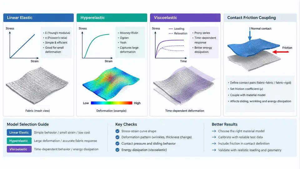
An airbag is not a rigid pressure vessel. It is a sewn membrane assembly of woven nylon or polyester fabric that unfolds, inflates, and interacts with an occupant within tens of milliseconds. The accuracy of any airbag CAE model therefore depends less on the gas dynamics than on how faithfully the fabric constitutive response and its frictional interaction with surrounding surfaces are represented. This chapter examines the three material-model families commonly available for airbag fabric — linear elastic, hyperelastic, and viscoelastic — and explains how each couples to contact friction definitions in an explicit solver such as LS-DYNA or Radioss.
Why Fabric Is Not a Simple Elastic Solid
Woven airbag fabric is a network of interlaced yarns. Its mechanical behavior is anisotropic, highly nonlinear, and rate-dependent. Under in-plane tension, the initial response is dominated by crimp interchange: yarns straighten before they stretch, producing a compliant toe region. Once the yarns are taut, the stiffness rises sharply. Coated fabrics (silicone or neoprene) add a further membrane contribution and reduce permeability. Any constitutive model must decide how much of this physics to capture, because the choice directly affects inflation pressure prediction, seam stress, and occupant contact force.
Three model families are available, and they form a natural hierarchy of fidelity versus calibration cost.
Linear Elastic Fabric Models
The simplest option treats the fabric as an orthotropic linear elastic shell. In LS-DYNA this is typically *MAT_ELASTIC or *MAT_ORTHOTROPIC_ELASTIC applied to *SECTION_SHELL elements. Two in-plane moduli (warp and weft), a shear modulus, and a thickness define the response. A representative starting point for uncoated nylon 6.6 fabric is:
*MAT_ORTHOTROPIC_ELASTIC
$   MID        RO         EA         EB         EC        PRBA
     1   1.15E-9     2.0E+3     2.0E+3     5.0E+1       0.30
$   GAB        GBC        GCA
   3.0E+1     3.0E+1     3.0E+1
Here RO is density in tonne/mm³, EA and EB are the warp and weft moduli in MPa, and GAB is the in-plane shear modulus. The linear model is fast, stable, and easy to calibrate from a single strip tensile test. Its weakness is that it cannot reproduce the crimp toe region or the stiffening at high strain, so it tends to over-predict stiffness at low pressure and under-predict it near full deployment. It is acceptable for early packaging studies or when the airbag is only a secondary load path, but it is a poor choice for occupant-out-of-position (OOP) simulations where the fabric must absorb energy accurately.
Hyperelastic Fabric Models
Hyperelastic models replace the constant stiffness with a strain-energy potential, capturing the nonlinear stiffening of the woven network. For airbag fabric, the most widely used formulation is the Ogden-type or the anisotropic hyperelastic model available as *MAT_FABRIC in LS-DYNA. *MAT_FABRIC is purpose-built for airbags: it accepts separate warp and weft stress–strain curves, a shear curve, and optional strain-rate scaling.
*MAT_FABRIC
$   MID        RO         EA         EB        EC        PRBA
     2   1.15E-9     0.0        0.0       0.0        0.30
$  LCA        LCB        LCC        LCS
     1          2          3          4
$  LCAB       LCBA       LCSDA      LCSDB
     5          5          0          0
Each load curve (LCA, LCB, LCS) is a tabulated engineering stress versus engineering strain curve measured from a uniaxial tensile test in the warp, weft, and shear directions respectively. Because the curves are entered directly, the model reproduces the toe region and the stiffening branch without analytical fitting. This is the recommended baseline for production airbag models. The trade-off is calibration effort: you need clean tensile data at the relevant strain rates, and the shear curve is often the hardest to obtain.
Viscoelastic Fabric Models
Viscoelasticity adds time dependence. Coated fabrics and fabrics under rapid deployment exhibit stress relaxation and rate-dependent stiffening. Two approaches exist. The first is a Prony-series viscoelastic overlay on a hyperelastic base, available through *MAT_VISCOELASTIC or by combining *MAT_FABRIC with a rate-dependent load-curve family. The second, and more common in airbag practice, is to define multiple stress–strain curves at different strain rates and let the solver interpolate. In *MAT_FABRIC this is done by supplying a rate-scaling curve via LCSDA or by using the *MAT_ADD_... rate options.
A practical rate-dependent setup uses three tensile curves measured at nominal strain rates of 0.01, 1, and 100 s⁻¹. The solver interpolates between them based on the current element strain rate. This captures the fact that a fabric loaded in 20 ms behaves stiffer than the same fabric loaded in 20 s. For most frontal airbag deployments, the strain rate in the fabric peaks between 10 and 200 s⁻¹, so the high-rate curve dominates the response.
Coupling Material Models to Contact Friction
The material model and the contact definition are not independent. Fabric slides against itself, against the module housing, and against the occupant. The friction coefficient at these interfaces changes the deployment kinematics and the seam loading. In LS-DYNA, fabric-to-fabric and fabric-to-rigid contact is defined with *CONTACT_AUTOMATIC_SINGLE_SURFACE or *CONTACT_AUTOMATIC_SURFACE_TO_SURFACE, with friction specified through *CONTACT_... card 2 or a *DEFINE_FRICTION curve.
*CONTACT_AUTOMATIC_SINGLE_SURFACE
$   SSID       MSID       SSTYP      MSTYP     SBOXID    MBOXID
     10         0          2          0         0         0
$     FS         FD         DC         VC         VDC
    0.20       0.20       0.0        0.0        0.0
The static friction coefficient FS and dynamic coefficient FD are typically 0.15–0.30 for coated fabric against itself, and 0.30–0.50 for fabric against metal or plastic housing. These values must be measured, not guessed, because a 0.1 change in friction can shift peak occupant chest deflection by several millimeters in an OOP simulation.
The coupling becomes important when the material model is rate-dependent. A viscoelastic fabric that stiffens at high strain rate will also generate higher normal forces at contact interfaces, which in turn increases the available friction force. If the friction coefficient is defined as constant, the model may under-predict the resistance to sliding during the rapid phase of deployment. A more faithful approach is to define friction as a function of contact pressure or sliding velocity using *DEFINE_FRICTION, though this requires additional tribology data.
Choosing the Right Model
The decision is driven by the simulation's purpose. For packaging and fold-pattern studies where the airbag is not the primary energy absorber, a linear orthotropic model with constant friction is sufficient and runs quickly. For occupant safety simulations, OOP, or any case where fabric stress and seam loading matter, use *MAT_FABRIC with measured warp, weft, and shear curves, and calibrate friction from coupon tests. Add rate dependence only when the deployment is fast enough that strain rate exceeds roughly 10 s⁻¹ in the fabric, which is true for most frontal and side airbags. The extra calibration cost is justified because the rate-dependent model changes both the inflation pressure history and the contact force transmitted to the occupant.
Practical Calibration Sequence
A reproducible workflow for a production airbag model follows four stages. First, obtain strip tensile data in warp, weft, and 45° bias directions at the target strain rates. Second, fit the *MAT_FABRIC load curves and run a single-shell-element verification at each rate; compare reaction force to the test curve and adjust until the toe and stiffening branches match within 5%. Third, build the full airbag model with *CONTACT_AUTOMATIC_SINGLE_SURFACE and an initial friction estimate from coupon tests. Fourth, run a deployment-only simulation (no occupant) and check that the inflation pressure history and the fabric stress at the seam match the physical test. If the pressure rises too slowly, the fabric is too compliant or the friction is too low; if the seam stress is excessive, the high-rate curve may be over-stiff. Iterate on friction and rate curves only after the material response is confirmed in isolation.
The key insight is that material model and contact friction are a coupled system. A hyperelastic fabric with constant friction will not reproduce the deployment of a viscoelastic fabric with rate-dependent friction, even if both are calibrated to the same quasi-static test. For any simulation where the airbag is the primary energy absorber, the viscoelastic option with measured rate curves and calibrated friction is the only choice that preserves both the inflation kinematics and the occupant load path.