1. Airbag deployment simulation landscape
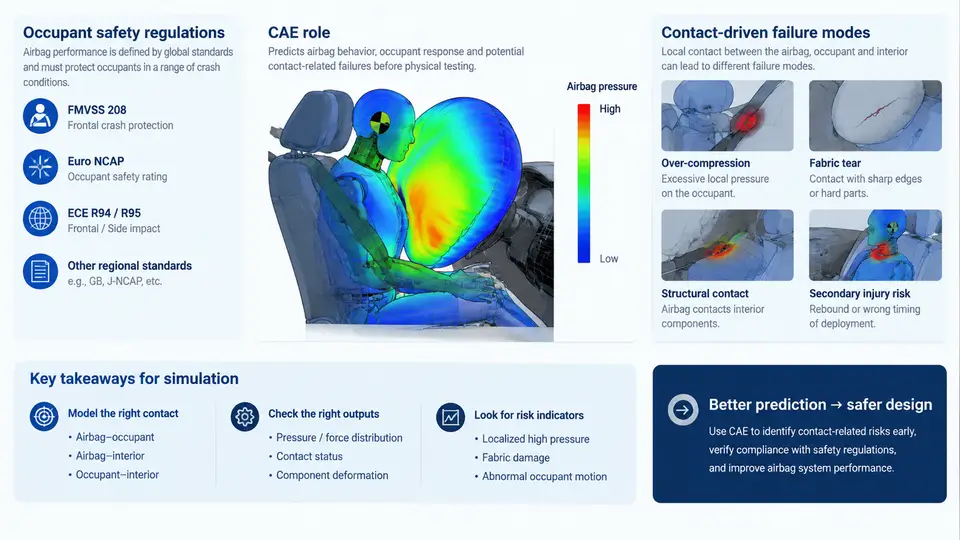
An airbag is a pyrotechnically driven, gas-inflated membrane that must deploy in tens of milliseconds, interact with a moving occupant, and then absorb energy without injuring that occupant. In CAE terms, this is not a structural problem, a fluid problem, or a multibody problem alone — it is a tightly coupled fluid–structure–contact problem in which the structure is a fabric membrane that folds, unfolds, and self-contacts. This chapter establishes the landscape: what regulations demand, where CAE sits in the development loop, and which failure modes are fundamentally contact-driven.
1.1 What the Regulations Actually Require
Regulatory and consumer-rating tests define the boundary conditions of every airbag simulation. The two dominant regimes are FMVSS 208 (US, occupant crash protection, including out-of-position and unbelted requirements) and the UN ECE R94/R95 family (Europe, frontal and side impact). Consumer programs — US NCAP, Euro NCAP, C-NCAP, JNCAP — add stricter injury criteria and, critically, low-risk deployment (LRD) and out-of-position (OOP) tests that directly stress the contact behavior of a deploying bag.
The measurable outputs are injury criteria, not forces: HIC15 and HIC36 for the head, Nij (neck injury criterion), chest deflection and viscous criterion (VC), and femur/ tibia loads. A typical frontal driver-side target set is HIC15 ≤ 700, chest deflection ≤ 42 mm, and Nij ≤ 1.0. These are evaluated at discrete time instants, so the simulation must resolve the full 0–120 ms event with enough temporal resolution to capture peak values.
| Regulation / Program | Key Test | Primary Contact Concern |
|---|---|---|
| FMVSS 208 | Unbelted 50 km/h rigid barrier, OOP static deployment | Bag–occupant contact force at close distance; bag punch-out |
| ECE R94 | 40% offset deformable barrier, 56 km/h | Bag–steering wheel / bag–A-pillar interaction |
| Euro NCAP LRD | Static deployment with 3-year-old / 6-year-old ATD at close proximity | Membrane self-contact during unfolding; early contact pressure |
| Side impact (R95 / NCAP) | Moving deformable barrier, pole test | Bag–door trim contact, bag–occupant gap closure |
1.2 Where CAE Sits in the Development Loop
Airbag CAE is not a single simulation; it is a chain. The chain typically runs: fold pattern definition → static deployment (inflator-only, no occupant) → OOP deployment → in-position occupant restraint → sled / full-vehicle validation. Each stage has a different dominant physics and a different contact challenge.
Static deployment isolates the bag: the inflator mass-flow curve drives inflation, and the only contact is bag self-contact plus bag-to-module/steering-wheel contact. This is where fold pattern and fabric permeability are calibrated. OOP deployment adds a stationary ATD at a defined distance (often 0–150 mm from the module) and is the harshest contact test — the bag strikes the ATD while still unfolding. In-position restraint adds occupant kinematics and belt interaction, where the bag must be fully deployed before the occupant arrives.
1.3 The Contact-Driven Failure Modes
Most airbag simulation failures that matter in practice are contact failures. They fall into four families:
- Self-contact / membrane interpenetration. During unfolding, fabric layers that should separate instead pass through each other. This produces non-physical pressure loss, a bag that inflates too slowly, and a late occupant contact. Root causes are usually insufficient contact thickness, a missing self-contact definition, or a time step too large relative to the fabric node velocity.
- Bag–occupant punch-through. The bag contacts the ATD at a single node or small patch, generating a local force spike. This is the classic OOP failure and shows up as a HIC or Nij outlier in a single run. It is a contact-stiffness and contact-area problem, not an inflation problem.
- Bag–structure snagging. The deploying bag catches on the steering-wheel rim, column shroud, or instrument-panel edge. The membrane then tears or the deployment path deviates. This is a geometric contact problem: the gap between module and surrounding trim must be modeled explicitly.
- Contact-induced instability. High-velocity contact between a light fabric shell and a heavy rigid body drives the explicit time step down or produces hourglassing in the fabric. The symptom is energy growth or a sudden drop in time step, not a visible geometric error.
1.4 A Reproducible Contact Check: Static Deployment Sanity Test
Before trusting any occupant result, run a static deployment sanity check. The goal is to confirm that the bag inflates to the expected volume and that self-contact is behaving. A minimal setup uses an inflator mass-flow curve, a folded fabric shell, and a rigid module box.
# Example: LS-DYNA-style static deployment control (illustrative values)
*CONTROL_TIMESTEP
   0.0,  0.9,  0.0,  0.0,  0.0
*CONTACT_AUTOMATIC_SINGLE_SURFACE
   1,  1,  0,  0,  0,  0,  0,  0
   0.0,  0.0,  0.0,  0.0,  0.0,  0.0,  0.0,  0.0
   0.0,  0.0,  0.0,  0.0,  0.0,  0.0,  0.0,  0.0
*MAT_FABRIC
   1,  1.2e-9,  0.0,  0.0,  0.0,  0.0,  0.0,  0.0
   0.0,  0.0,  0.0,  0.0,  0.0,  0.0,  0.0,  0.0
*AIRBAG_SIMPLE_PRESSURE_VOLUME
   1,  1,  1,  0.0,  0.0,  0.0,  0.0,  0.0
   0.0,  0.0,  0.0,  0.0,  0.0,  0.0,  0.0,  0.0
Run the model for 60 ms and inspect three things. First, the bag volume curve should rise monotonically and plateau near the design volume (for a driver bag, roughly 60–70 L). Second, the internal pressure should peak early and then decay as the bag vents — a pressure that keeps rising after 40 ms usually means self-contact is trapping gas. Third, the total energy should stay bounded; a sudden jump indicates contact instability. If the bag volume plateaus at 40 L instead of 65 L, the most likely cause is membrane interpenetration during unfolding, and the fix is to increase contact thickness or reduce the initial time step.
1.5 What This Means for the Rest of the Course
The regulatory targets are fixed, but the path to meeting them runs through contact. Every later chapter — fold pattern generation, fabric material calibration, inflator modeling, OOP setup, and occupant restraint tuning — either feeds a contact definition or is validated by a contact-driven result. The failure modes introduced here (self-contact, punch-through, snagging, instability) are the diagnostic vocabulary you will use throughout. When a simulation misbehaves, the first question is always: which contact is not behaving, and what does the energy and pressure history say about it?
With the landscape established, the next step is to look at the fabric itself — how a woven airbag material is represented, and why its permeability and stiffness determine whether the contact model can ever be stable.