1. Airbag CAE in the product development li
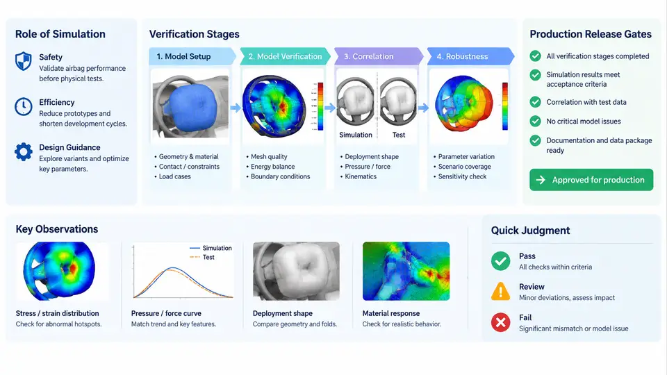
In an occupant safety program, the airbag CAE model is not a one-off analysis artifact. It is a living engineering asset that evolves alongside the restraint system, the vehicle body, and the occupant package. Its credibility determines whether physical sled and barrier tests confirm the CAE prediction, and ultimately whether the program can pass the production release gate. Understanding where CAE sits in the development lifecycle — and what each verification stage demands of the model — is the foundation for everything that follows in this course.
The Role of Simulation in Restraint Development
Airbag CAE serves three distinct purposes across a vehicle program. First, it supports concept selection: comparing bag volume, venting strategy, tether configuration, and inflator output before any hardware exists. Second, it drives design convergence: iterating module geometry, fold pattern, and deployment timing against occupant injury criteria such as HIC, chest deflection (Dmax), and neck injury metrics. Third, it provides evidence for certification: demonstrating compliance with FMVSS 208, ECE R94/R95, or C-NCAP/Euro NCAP protocols through validated models rather than exhaustive physical testing.
These three purposes impose different fidelity requirements. A concept study tolerates a coarse bag mesh and a lumped inflator model. A certification submission does not. The model must be traceable, version-controlled, and validated against physical test data at the same configuration it claims to represent.
Verification Stages and Their Gates
Most OEMs structure airbag CAE verification into a staged progression, each stage acting as a gate that must be cleared before the next begins. The stages are not arbitrary; each one isolates a specific source of uncertainty so that failures can be attributed correctly.
| Stage | Primary Objective | Typical Inputs | Exit Criterion |
|---|---|---|---|
| Component / subsystem | Validate bag deployment kinematics and inflator output | Static deployment test, tank test pressure curve | Bag shape and timing within agreed tolerance |
| Sled (body block / buck) | Validate occupant kinematics and restraint interaction | Sled pulse, belt geometry, seat position | Head/chest acceleration correlation within 15% |
| Full vehicle barrier | Confirm system-level performance with body deformation | Barrier test, vehicle deceleration pulse | Injury criteria margin ≥ 10% below limit |
| Production release | Freeze model and demonstrate robustness | Final CAD, validated material cards, sign-off matrix | All gates closed, model archived and locked |
The critical discipline here is one variable at a time. If a sled model fails to correlate, the cause could be the inflator mass flow rate, the bag permeability, the fold pattern, or the belt routing. Component-level validation removes the inflator and bag uncertainties first, so that sled correlation failures point to occupant packaging or belt behavior rather than the airbag itself.
Production Release Gates
A production release gate is a formal checkpoint where the CAE model is declared fit for its intended use. It is not simply "the analysis is finished." The gate requires documented evidence across several dimensions:
- Geometric fidelity: the model represents the released CAD, including the as-built fold pattern and module packaging.
- Material and inflator data: fabric permeability, seam strength, and inflator pressure curves are traceable to test reports, not handbook values.
- Correlation status: each verification stage has a correlation report with quantified error against physical test.
- Robustness: the model has been exercised across the production tolerance envelope — inflator output ±5%, ambient temperature extremes, seat position range, and occupant size variation.
- Configuration control: the model revision is locked, and any subsequent change requires a formal deviation and re-validation.
How the Stages Connect: A Data and Decision Flow
The diagram below shows how information flows between verification stages and where the release gate sits. Note that each stage feeds both forward (to the next stage) and backward (to design iteration). The release gate is not a single point but a convergence of evidence from all prior stages.
What "Validated" Actually Means
A validated airbag CAE model is one whose predictions have been compared against physical test data at a defined configuration, with quantified error, and whose intended use is explicitly stated. Validation is not a binary property. A model validated for 50th percentile male occupant in a frontal 56 km/h barrier test is not automatically valid for a 5th percentile female in a 32 km/h offset deformable barrier test. The release gate must therefore document the validation matrix: which configurations were correlated, which were extrapolated, and what the confidence level is for each.
In practice, this means the CAE engineer maintains a correlation table that maps each physical test to its corresponding simulation, the key response variables compared (head acceleration, bag pressure, belt force), and the percentage deviation. A typical acceptance threshold for sled correlation is 15% on peak head acceleration and 10% on bag internal pressure timing. These are not universal constants; they are program-specific agreements between CAE, test, and safety engineering.
Why This Matters for the Rest of the Course
Every subsequent topic — mesh quality, fold modeling, inflator characterization, contact definition, correlation metrics — exists to serve the lifecycle described here. A model that cannot pass its stage gates is not a useful engineering asset, regardless of how refined its mesh or how sophisticated its material cards. The production release gate is the final arbiter: it asks not "does the model run?" but "can we defend every prediction it makes?"
With this lifecycle context established, the next step is to examine the specific modeling decisions that determine whether an airbag CAE model can meet these gates — beginning with the geometric and topological requirements of the occupant safety model.