3. Vehicle side structure modeling
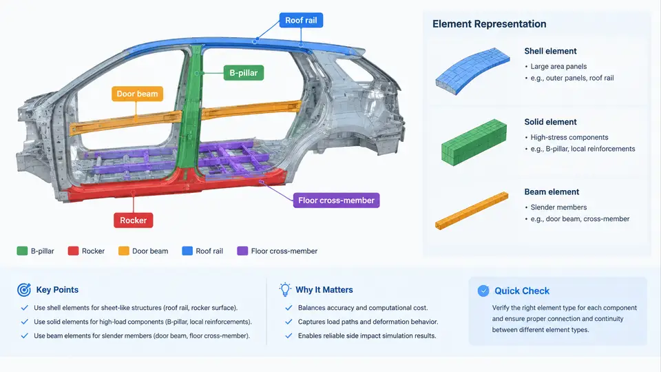
In a PAM-CRASH side impact model, the structural fidelity of the body side determines whether the simulation can reproduce the intrusion pattern that governs occupant injury. The five components discussed here — B-pillar, rocker (sill), door beam (side impact beam / intrusion beam), roof rail, and floor cross-member — form the primary load path that transfers barrier energy from the struck side into the rest of the body-in-white (BIW). This section explains how to represent each of them with shell, solid, and beam elements, and how to choose the right discretization for the physics you need to capture.
Element Type Selection: Shell, Solid, or Beam
The decision is driven by the through-thickness stress state and the geometric aspect ratio of the part.
- Shell elements (4-node, Belytschko-Tsay or fully integrated): the default for thin-walled stamped panels — B-pillar outer/inner, rocker panels, roof rail, door beam (if tubular thin-wall), and floor cross-member. They carry membrane and bending loads efficiently and are computationally cheap. Use 5 through-thickness integration points for elastic-plastic bending; increase to 7 if you expect severe springback or through-thickness yielding.
- Solid elements (8-node hexahedron): required where the part is thick relative to its other dimensions, or where contact pressure and through-thickness stress matter — e.g., a cast aluminum B-pillar hinge reinforcement, a hydroformed rocker insert, or a foam-filled rocker section. Solid meshes are also used for the barrier and for rigid impactor surfaces.
- Beam elements (Hughes-Liu or Belytschko-Schwer): appropriate for slender members whose cross-section is small compared to length and whose dominant response is axial/bending — door beam tubes, seat mounting rails, or simplified cross-car braces. Beams are also used for spot-weld and bolt connectors between panels.
B-Pillar
The B-pillar is the most critical intrusion-resisting member. Model the outer panel, inner panel, and any reinforcement as separate shell layers connected by spot welds. A typical mesh uses 5–8 mm target element size in the impact zone and 10–15 mm elsewhere. The weld flange between outer and inner panels should be represented by either shared nodes (if the mesh is coincident) or by beam/spring connectors with a failure criterion.
Material definition matters more than mesh density here. For a hot-stamped B-pillar (e.g., 22MnB5, 1500 MPa tensile), use a strain-rate-dependent plasticity model such as MAT_36 (PAM-CRASH material 36, Johnson-Cook) or MAT_103 (isotropic elastic-plastic with damage). Define the flow curve from the actual forming simulation if available; otherwise use the as-supplied true stress–true strain curve. The failure strain for hot-stamped steel is typically 5–8%; for mild steel B-pillar grades it can exceed 20%.
Rocker (Sill)
The rocker is a closed box section formed by the rocker outer, rocker inner, and often a rocker reinforcement. Because it is a closed section, model it with shells on all faces — do not replace it with a single equivalent beam unless you are doing a concept-level study. The spot welds along the top and bottom flanges control the section's ability to resist bending. Use a weld failure model (e.g., MAT_100 or a tied contact with failure) so that weld separation can occur under extreme intrusion.
If the rocker contains structural foam or a hydroformed aluminum insert, represent the foam with solid elements using a crushable foam material (MAT_50 or MAT_63) and the insert with shells or solids depending on wall thickness. The foam–steel interface should use a tied contact or shared nodes.
Door Beam
The door beam is a slender, often tubular member spanning the door aperture. For a steel tube of 30–40 mm diameter and 1.5–2.5 mm wall thickness, shell modeling of the tube is preferred if you need to capture local buckling and ovalization. Use 4–6 mm element size around the circumference and along the length. If the beam is a simple solid bar or a closed section where global bending dominates, a beam element with an equivalent section (area, Iyy, Izz, J) is acceptable and much cheaper.
Connect the beam ends to the door frame or B-pillar/rocker using rigid bodies or beam connectors that represent the mounting brackets. These connections are frequent failure points; if they are not modeled with a realistic strength, the beam will appear to carry load it cannot in reality.
Roof Rail and Floor Cross-Member
The roof rail is a thin-walled closed section similar to the rocker. Model it with shells, paying attention to the A-pillar/B-pillar/roof rail joint, which is a common location for spot-weld failure and panel separation. The floor cross-member (seat cross-member, tunnel cross-member) is typically a hat-section stamped panel welded to the floor pan. Use shells with a mesh size of 8–12 mm. If the cross-member is a closed box formed with the floor pan, include the floor pan in the model — do not treat the cross-member as an isolated beam.
Connection Modeling: Spot Welds and Structural Adhesive
Spot welds are the weakest link in most side structures. Represent each weld with a beam element (often a 2-node beam with a circular cross-section of 4–5 mm diameter) or a solid hexahedron if the mesh is fine enough. Use a failure criterion based on the weld nugget diameter and the sheet thickness. For structural adhesive, use a cohesive zone model or a tied contact with a traction–separation law.
Practical Modeling Workflow and Verification
A reproducible workflow for one side structure sub-assembly is:
- Import the CAD geometry and mid-surface the panels. Check for gaps and overlaps; repair before meshing.
- Mesh each panel with shells. Target 6 mm in the impact zone, 12 mm elsewhere. Use a growth rate below 1.2.
- Assign thickness per element from the CAD or from the stamping thickness map. Do not use a single nominal thickness for a tailored blank.
- Create spot-weld beams at the flange locations. Assign a failure criterion (e.g., force-based or strain-based).
- Define materials with strain-rate dependence. For steel, use a Cowper-Symonds or Johnson-Cook model.
- Set up contacts: self-contact within the side structure, and contact with the barrier and occupant compartment.
- Run a short verification simulation — a static or low-speed push on the B-pillar — and check that the force–displacement response matches the expected stiffness. If the model is too stiff, check for merged nodes or missing welds. If it is too soft, check for unconnected panels or missing thickness.
Typical failure symptoms and their causes: (a) B-pillar folds at a weld line instead of forming a plastic hinge — the weld is too strong or the mesh is too coarse; (b) rocker separates from the floor — missing or failed welds; (c) door beam pushes through the door trim without bending — the beam material is too stiff or the connection is rigid; (d) roof rail tears at the A-pillar joint — insufficient weld representation or missing adhesive.
The diagram above summarizes the load path: the barrier strikes the door beam and B-pillar, which transfer force into the rocker and roof rail, and then into the floor cross-member. Each member's element type and connection strategy must be chosen to preserve this path. A model that is too stiff in the B-pillar or too soft in the rocker will misrepresent the intrusion velocity and the resulting occupant loading.
Key Modeling Parameters Summary
| Component | Preferred element | Typical mesh size | Critical modeling detail |
|---|---|---|---|
| B-pillar | Shell (5–7 IP) | 5–8 mm impact zone | Weld failure, strain-rate material |
| Rocker | Shell (closed box) | 6–10 mm | Flange welds, foam/insert if present |
| Door beam | Shell or beam | 4–6 mm (shell) | End bracket strength, buckling |
| Roof rail | Shell | 8–12 mm | A/B-pillar joint welds |
| Floor cross-member | Shell (hat section) | 8–12 mm | Include floor pan, weld line |
After building the side structure, run a verification load case: apply a 50 mm quasi-static displacement to the B-pillar at 100 mm/s and check that the reaction force at the rocker and roof rail is within 10% of the expected stiffness from a physical test or a validated full-vehicle model. If the force is too high, inspect for merged nodes or missing weld failure. If too low, check for unconnected panels or incorrect thickness. This step catches most modeling errors before the full side impact simulation.