1. Production model verification and releas
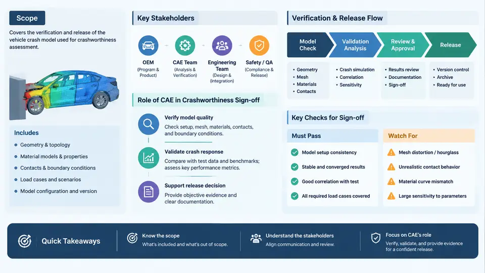
In vehicle crashworthiness engineering, the gap between a validated CAE model and a production-ready simulation asset is wider than most teams initially expect. A model that correlates well with a single sled test or a simplified barrier impact is not automatically qualified to support a formal design release decision. Production model verification and release is the disciplined process that closes this gap: it confirms that the PAM-CRASH model represents the current production design intent, that its setup conforms to the program's simulation guidelines, and that its predictive behavior has been demonstrated against physical test evidence within an accepted tolerance band. Only after this confirmation can CAE results be used as a formal input to crashworthiness sign-off.
What "Production Model" Means in This Context
A production model in PAM-CRASH is not merely a mesh with material cards. It is a configuration-controlled simulation asset that must satisfy several conditions simultaneously:
- Design intent fidelity: The geometry, material grades, gauge thicknesses, joining methods (spot welds, adhesives, bolts, laser welds), and structural architecture match the released CAD data and the bill of materials for the specific build phase.
- Setup conformity: Boundary conditions, initial velocity, barrier geometry, contact definitions, hourglass control, time-step settings, and output requests follow the program's CAE simulation standard.
- Correlation evidence: The model has been validated against at least one relevant physical test — full frontal, offset deformable barrier (ODB), side pole, or rear impact — with documented comparison of intrusion, acceleration, and deformation metrics.
- Traceability: Every change to the model is recorded with a revision identifier, the reason for change, the responsible engineer, and the date. The released version is frozen and archived.
The distinction matters because a model can be numerically stable and visually plausible while still being unqualified for release. A missing weld in a critical load path, an outdated material card for a high-strength steel grade, or a barrier positioned 10 mm off specification can shift predicted intrusion by tens of millimeters — enough to change a pass/fail judgment.
Scope of Verification and Release
The verification scope is defined by the program's crashworthiness requirements and the specific load cases that CAE must support. In a typical passenger vehicle program, this includes:
| Load Case | Primary CAE Output | Typical Acceptance Reference |
|---|---|---|
| Full frontal rigid barrier (56 km/h) | B-pillar acceleration, toe pan intrusion, steering column displacement | Program targets derived from regulatory and internal requirements |
| Offset deformable barrier (64 km/h, 40% overlap) | Footwell intrusion, dash panel displacement, door aperture deformation | Structural integrity and occupant survival space criteria |
| Side pole impact (32 km/h, 75°) | Door intrusion velocity, B-pillar deformation, seat mount displacement | Side airbag deployment timing and occupant clearance |
| Rear impact (80 km/h, 70% overlap) | Fuel system integrity, rear structure crush, seat back strength | Regulatory and internal fuel system protection targets |
Each load case carries its own verification checklist. The release decision is not global — a model may be released for frontal analysis while still under correlation review for side impact. This granularity prevents premature use of unvalidated load paths.
Stakeholders and Their Responsibilities
Production model release is a cross-functional gate. The key stakeholders and their roles are:
- CAE engineer: Builds, updates, and documents the model; runs correlation studies; prepares the release package.
- CAE method group / simulation governance: Owns the simulation standard, checks compliance, and maintains the release database.
- Body-in-white (BIW) design engineer: Confirms that the model reflects the latest CAD release and flags pending design changes.
- Test engineer: Provides physical test data, instrumentation layout, and boundary condition documentation for correlation.
- Crashworthiness attribute leader: Uses the released model for performance assessment and signs off on its fitness for the specific attribute decision.
- Program management: Tracks release status against vehicle program milestones and escalates delays.
The release gate is typically formalized as a checklist review meeting or a digital sign-off workflow. The CAE engineer does not unilaterally declare a model "released" — the method group verifies compliance, and the attribute leader confirms that the model is fit for the intended decision.
The Role of CAE in Crashworthiness Sign-Off
Crashworthiness sign-off is the formal confirmation that a vehicle design meets its safety targets. CAE contributes to this sign-off in three distinct ways:
- Predictive assessment: Before physical prototypes exist, CAE predicts whether the design will meet intrusion, acceleration, and structural integrity targets. These predictions guide design decisions and reduce the number of physical test iterations.
- Root cause analysis: When a physical test fails, CAE helps isolate the contributing structure, load path, or joining method. A verified production model can be interrogated to understand why a particular deformation mode occurred.
- Design change evaluation: When a late design change is proposed — a gauge increase, a weld pattern modification, a material substitution — CAE evaluates the impact on crash performance without waiting for a new physical test.
For CAE to carry this weight, the model must be verified and released. An unverified model can produce results that are numerically valid but physically misleading. The release process ensures that the model's predictive capability has been demonstrated, its limitations are documented, and its configuration is frozen for the specific decision at hand.
Key principle: A PAM-CRASH model is not "released" because it runs without errors. It is released because its correlation against physical test evidence has been reviewed, its setup conforms to the program standard, and its configuration is traceable to the current design intent.
Practical Verification Workflow
The following workflow represents a typical verification and release sequence for a frontal impact model. It is presented as a reproducible example; actual parameters and tolerances must be adapted to the program's specific requirements.
Step 1 — Model freeze and baseline run
  Input:  PAM-CRASH model at revision R12, frontal barrier setup
  Action: Run baseline simulation with standard output requests
  Output: Baseline result set (intrusion, acceleration, energy curves)

Step 2 — Physical test data preparation
  Input:  Test report T-2024-FR-003, accelerometer and displacement data
  Action: Filter test data per SAE J211, align time zero, extract key metrics
  Output: Reference curves for B-pillar acceleration and toe pan intrusion

Step 3 — Correlation comparison
  Input:  Baseline CAE results, filtered test data
  Action: Overlay curves, compute peak value deviation and phase shift
  Output: Correlation table (see example below)

Step 4 — Model adjustment (if required)
  Input:  Correlation table, engineering judgment
  Action: Adjust material parameters, weld representation, or contact stiffness
  Output: Revised model revision R13 with change log

Step 5 — Release review
  Input:  Correlation report, compliance checklist, change log
  Action: Method group and attribute leader review
  Output: Release approval or conditional release with documented limitations
An example correlation table for a frontal impact model might look like this:
| Metric | Test Value | CAE Value | Deviation | Status |
|---|---|---|---|---|
| B-pillar peak acceleration | 42.3 g | 44.1 g | +4.3% | Pass (≤10%) |
| Toe pan max intrusion | 118 mm | 126 mm | +6.8% | Pass (≤15%) |
| Steering column displacement | 72 mm | 65 mm | −9.7% | Pass (≤15%) |
| Time of peak acceleration | 58 ms | 54 ms | −4 ms | Review (≤5 ms) |
In this example, the time-of-peak deviation is flagged for review because it exceeds the program's phase tolerance. This does not necessarily block release, but it must be documented and understood — perhaps the model's front rail buckling sequence differs slightly from the test, which could affect the reliability of timing-sensitive outputs such as airbag deployment predictions.
Practical note: Correlation tolerances are not universal. A program may accept ±10% on peak acceleration but only ±5% on intrusion, depending on which metric drives the safety decision. Always confirm the tolerance table before starting correlation work.
Common Failure Modes in Model Verification
Several issues repeatedly appear during production model verification:
- Stale geometry: The model was built from an older CAD release, and a recent design change (e.g., a reinforced B-pillar inner) is missing. Symptom: CAE underpredicts side impact performance. Fix: Compare model geometry against the latest CAD release and update affected parts.
- Incorrect material card: A high-strength steel grade is represented by a mild steel card, or the strain-rate dependency is omitted. Symptom: CAE shows excessive deformation in a region that performs well in test. Fix: Verify material cards against the program's material database and test certificates.
- Weld omission or duplication: Spot welds are missing along a critical load path, or duplicate welds create artificial stiffness. Symptom: Localized deformation pattern differs from test. Fix: Cross-check weld locations against the joining specification and use a weld audit script.
- Boundary condition mismatch: The barrier height, impact angle, or initial velocity differs from the test setup. Symptom: Global response deviates in a consistent direction. Fix: Reconcile the CAE setup against the test request and instrumentation report.
Each of these failure modes is detectable through systematic verification. The release process exists precisely to catch them before CAE results influence a sign-off decision.
What the Released Model Enables
Once a production model is verified and released, it becomes a trusted asset for the program. It can be used to:
- Support design release decisions with quantified confidence.
- Evaluate late design changes without waiting for physical tests.
- Investigate test failures and propose countermeasures.
- Provide input to occupant safety simulations and restraint system tuning.
- Build a correlation history that improves future model quality.
The release is not the end of the model's life — it is the point at which the model becomes a reliable engineering tool. Subsequent design changes will require re-verification, and the release status must be maintained as the design evolves. The discipline of verification and release is what separates a simulation that merely runs from a simulation that can be trusted.
The diagram above shows how the six stakeholder groups interact with the release gate. Each group contributes a specific input — model build, compliance check, design confirmation, test evidence, attribute fitness, and program tracking — and the gate produces a released model that can be used as a formal input to crashworthiness sign-off. The release gate is not a single event but a controlled state that must be maintained as the design evolves.