1. Pedestrian protection crash simulation w
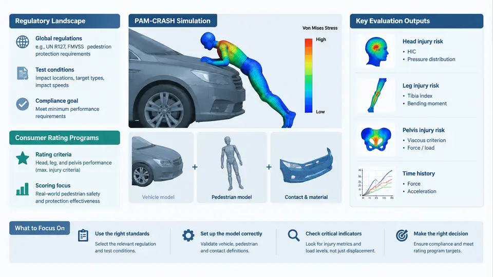
Pedestrian protection simulation sits at the intersection of vehicle body engineering, materials science, and biomechanics. Before a single finite element model is built, the CAE engineer must understand why the simulation exists: which regulations impose hard pass/fail limits, which consumer programs drive competitive ratings, and how those external requirements translate into concrete engineering targets for the front-end structure. This chapter establishes that foundation and frames the role of PAM-CRASH as the explicit solver used throughout the course.
1.1 The Regulatory Framework
Two regulatory families dominate global pedestrian protection requirements. The UN ECE Regulation No. 127 (formerly R127, succeeding the older R127/00 and the earlier Directive 2003/102/EC in Europe) defines type-approval tests for both adult and child pedestrian head impacts, upper-leg impacts against the bonnet leading edge, and lower-leg impacts against the bumper. The Global Technical Regulation No. 9 (GTR No. 9) provides a harmonized alternative adopted in several markets, including Japan and Korea, with a flexible phase-in schedule.
In parallel, the FMVSS 228 in the United States addresses pedestrian protection through a different mechanism, and China's GB/T 24550 establishes its own headform and legform test matrix. The practical consequence for simulation is that a single vehicle program may need to satisfy multiple, non-identical impact point grids, each with its own velocity, angle, and injury threshold.
| Regulation / Program | Head Impact Criterion | Leg Impact Criterion | Key Differentiator |
|---|---|---|---|
| UN ECE R127 | HIC ≤ 1000 (adult & child zones) | Bending angle ≤ 19°, shear ≤ 6 mm; upper leg ≤ 220 Nm | Mandatory type approval in EU/UN markets |
| GTR No. 9 | HIC ≤ 1000 (phase-dependent) | Same legform limits as R127 | Harmonized global alternative; flexible phase-in |
| Euro NCAP | HIC ≤ 650 for maximum score; 1000 = zero score | Scored against bending/shear; upper leg scored | Star rating drives consumer choice |
| C-NCAP | HIC thresholds aligned with Euro NCAP | Legform scoring with local grid | China market rating |
The critical engineering insight is that consumer programs are stricter than regulation. Euro NCAP awards points on a sliding scale: a HIC of 650 or below earns full marks, while 1000 yields zero. This means a vehicle that merely passes R127 may still score poorly in consumer testing, directly affecting market competitiveness. Simulation targets must therefore be set against the most demanding applicable program, not the regulatory minimum.
1.2 Consumer Rating Programs and Their Scoring Logic
Euro NCAP's pedestrian protection assessment divides the front end into discrete impact zones. The headform test grid covers the bonnet top, wings, and A-pillar region, with each grid point assigned to either the adult or child headform based on the wrap-around distance (WAD) from the ground reference. The legform tests target the bumper and the bonnet leading edge.
Scoring is zone-weighted. A typical Euro NCAP pedestrian score sheet might show:
- Head impact: 24 points maximum, distributed across the bonnet grid. Each grid point contributes proportionally to its zone area.
- Upper leg: 6 points, assessed at the bonnet leading edge.
- Lower leg: 6 points, assessed at the bumper.
For simulation, this means the CAE engineer must reproduce the exact impact point coordinates, impactor geometry, and impact velocity specified by the program. A headform impact at 40 km/h with a 65 mm diameter sphere is not the same as a 35 km/h impact with a 165 mm diameter sphere — the deformation mode and HIC response differ substantially.
1.3 Engineering Objectives and the Role of PAM-CRASH
The engineering objective is not merely to pass a test but to design a front-end structure that manages impact energy across a wide range of pedestrian sizes, postures, and impact speeds. This requires a simulation tool capable of capturing:
- Large deformation and contact: The bonnet outer panel undergoes significant bending and local indentation. PAM-CRASH's explicit time integration and robust contact algorithms handle the self-contact and sliding contact between the headform, bonnet, and underlying components.
- Material nonlinearity: Aluminum bonnets, high-strength steel hinges, and plastic bumper fascia each exhibit different strain-rate sensitivity. PAM-CRASH supports rate-dependent material models (e.g., Johnson-Cook, Cowper-Symonds) that are essential for accurate force–displacement prediction.
- Kinematic consistency: The headform must be positioned and oriented exactly as specified by the regulation or rating program. PAM-CRASH's rigid body and initial velocity definitions allow precise control of impactor kinematics.
A typical PAM-CRASH pedestrian head impact model consists of the following input blocks:
/RUNBEGIN
  TITLE = "Pedestrian Head Impact - Bonnet Grid Point A3"
  DTINIT = 1.0E-6
  TEND = 0.030
/RUNEND

/MAT/LAW36/1
  RO = 2.7E-9
  E = 70000.0
  PR = 0.33
  SIGY = 180.0
  EH = 500.0

/PART/1
  MAT = 1
  THICK = 1.2

/INIVEL/1
  VX = 0.0
  VY = -11.11
  VZ = 0.0

/CONTACT/TYPE7/1
  SLAVE = 10
  MASTER = 20
  FRIC = 0.3
In this example, the headform is assigned an initial velocity of 11.11 m/s (40 km/h) in the negative Y direction, consistent with a vertical impact on the bonnet. The bonnet material is modeled with a rate-independent plastic law for initial scoping; a rate-dependent law would be substituted for final validation. The contact definition uses PAM-CRASH's TYPE7 penalty-based contact, which is well-suited for the large sliding and separation observed in pedestrian impacts.
1.4 From Requirements to Simulation Targets: A Worked Example
Consider a vehicle program targeting both UN ECE R127 type approval and a five-star Euro NCAP rating. The CAE engineer must define a simulation matrix that covers:
- Adult headform impacts at 40 km/h, 65 mm diameter, across the bonnet top and wings.
- Child headform impacts at 40 km/h, 165 mm diameter, across the bonnet leading edge and bumper region.
- Upper legform impacts at 40 km/h against the bonnet leading edge.
- Lower legform impacts at 40 km/h against the bumper.
Each impact point is simulated independently. The output of interest is the HIC value for head impacts, and the bending angle and shear displacement for leg impacts. The engineer compares these against the target thresholds and iterates on the design — adjusting bonnet thickness, adding energy-absorbing foam, or modifying hinge geometry — until all points meet the target with sufficient margin.
1.5 Visual Overview of the Simulation Workflow
The following diagram summarizes the relationship between regulatory requirements, consumer programs, and the PAM-CRASH simulation workflow. It is not a linear flowchart but a dependency map: the regulatory and rating inputs define the simulation matrix, which in turn drives the model setup and result evaluation.
1.6 Summary
This chapter has established the three pillars that define pedestrian protection simulation with PAM-CRASH: the regulatory landscape (UN ECE R127, GTR No. 9, GB/T 24550), the consumer rating programs (Euro NCAP, C-NCAP, JNCAP) that impose stricter scoring thresholds, and the engineering objectives that translate these external requirements into simulation targets. The key takeaway is that simulation must be driven by the most demanding applicable requirement, with explicit margin policies to account for real-world variability. PAM-CRASH provides the explicit solver, contact algorithms, and material models needed to predict headform HIC and legform bending/shear responses with sufficient fidelity to guide front-end design decisions.