1. Multi-impact crashworthiness fundamental
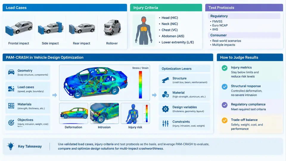
Multi-impact crashworthiness is the discipline of ensuring that a vehicle structure protects occupants across a sequence of distinct collision events, not just a single idealized impact. In real-world accidents, a vehicle may strike a barrier, rebound, and then be struck again from a different direction; it may roll over after an initial frontal hit; or it may experience a low-speed bumper impact followed by a high-severity pole strike. Each event imposes different loading paths, deformation modes, and occupant kinematics. Designing for only one of them can leave the structure optimized for a scenario that rarely occurs in isolation.
PAM-CRASH, an explicit finite element solver widely used in the automotive industry, is the primary simulation tool in this course. It solves the nonlinear dynamic equations of motion for a discretized vehicle model, capturing large deformations, contact, material failure, and occupant response. Its role in multi-impact design optimization is to let engineers evaluate hundreds of load-case combinations before a single physical prototype is built, then to guide the selection of thicknesses, materials, and structural topology that satisfy all required performance targets simultaneously.
Load Cases and Their Physical Meaning
A load case is a defined set of initial conditions, boundary conditions, and impact parameters that represent one crash scenario. The most common load cases in vehicle development are:
- Full frontal rigid barrier — 100% overlap, 56 km/h (or 64 km/h for some regions), used to assess restraint system and front-end energy absorption.
- Offset deformable barrier (ODB) — 40% overlap, 64 km/h, which concentrates deformation on one side and is more sensitive to structural asymmetry.
- Side impact — a moving deformable barrier strikes the driver or passenger side at 50–60 km/h, testing door intrusion and side airbag performance.
- Rear impact — a moving barrier strikes the rear at 80 km/h, evaluating seat integrity and whiplash protection.
- Pole impact — a narrow rigid pole strikes the side or front, creating high local pressure and often causing more severe intrusion than a flat barrier.
- Rollover — quasi-static roof crush or dynamic rollover, assessing roof strength and occupant retention.
In a multi-impact sequence, these cases are not independent. A frontal impact may rotate the vehicle and shift its center of gravity, changing the effective impact angle for a subsequent side or rear event. The structure may already be partially crushed, reducing its residual stiffness and altering load paths. PAM-CRASH models this by allowing the deformed mesh from one event to be used as the initial state for the next, preserving residual stresses and geometric imperfections.
Injury Criteria and Regulatory Targets
Crashworthiness is ultimately judged by occupant injury metrics. The most widely used criteria are:
| Criterion | Definition | Typical Threshold |
|---|---|---|
| HIC (Head Injury Criterion) | Integral of resultant head acceleration over a time window | HIC₁₅ ≤ 700 (FMVSS 208), ≤ 1000 (ECE R94) |
| Chest deflection | Maximum sternum-to-spine compression | ≤ 50 mm (Euro NCAP), ≤ 75 mm (FMVSS 208) |
| Femur force | Axial load transmitted through the femur | ≤ 10 kN (FMVSS 208) |
| Nij (Neck Injury) | Combined axial force and bending moment | ≤ 1.0 (Euro NCAP) |
| VC (Viscous Criterion) | Rate of chest compression times compression | ≤ 1.0 m/s |
These thresholds are not arbitrary. They are derived from biomechanical studies and epidemiological data, and they differ between regulatory regimes. FMVSS 208 in the United States, ECE R94 in Europe, and China's GB 11551 each specify different barrier types, speeds, and occupant sizes. Consumer programs such as Euro NCAP, C-NCAP, and IIHS add further requirements, often with higher speeds or more severe offset configurations. A vehicle designed only to pass one regulation may fail another, which is why multi-impact optimization must consider the full set of applicable protocols.
Regulatory and Consumer Test Protocols
Regulatory tests are pass/fail and legally mandated. Consumer tests are voluntary but influence market perception and insurance ratings. The key difference is that consumer protocols evolve faster and often include more severe or novel load cases. For example, IIHS introduced the small overlap frontal test (25% overlap, 64 km/h) because vehicles that performed well in 40% ODB tests were still causing severe leg and foot injuries in narrow-offset crashes. Euro NCAP added a far-side occupant protection assessment and a mobile progressive deformable barrier (MPDB) test to address compatibility between vehicles of different masses.
In PAM-CRASH, each protocol is represented by a specific model setup: barrier geometry, initial velocity, contact definitions, and occupant positioning. The solver then computes the structural response and the resulting injury values. The optimization loop adjusts design variables — such as sheet metal thickness, material grade, bead patterns, and joint stiffness — until all criteria are satisfied with adequate margin.
Role of PAM-CRASH in Design Optimization
PAM-CRASH is not just a solver; it is part of a workflow that includes pre-processing (mesh generation, material definition, boundary conditions), solving, and post-processing (injury metric extraction, deformation visualization). In multi-impact optimization, the workflow typically follows these steps:
- Build a baseline finite element model of the vehicle body-in-white and occupant restraint system.
- Define the load cases and their sequence, including any pre-deformation from prior impacts.
- Run the baseline simulation and extract injury metrics and structural responses.
- Identify design variables and their allowable ranges.
- Use an optimization algorithm (e.g., genetic algorithm, response surface method) to generate candidate designs.
- Run PAM-CRASH for each candidate, evaluate constraints, and iterate.
- Validate the final design with a full multi-impact simulation and, eventually, physical testing.
The key advantage of PAM-CRASH in this context is its explicit time integration scheme, which handles the high-speed, large-deformation nature of crash events without convergence issues. It also supports advanced material models for steel, aluminum, composites, and plastics, and it can couple with occupant simulation tools such as MADYMO or its own occupant models.
Practical note: When setting up a multi-impact sequence in PAM-CRASH, always verify that the deformed mesh from the first impact is properly mapped to the second impact model. Residual stresses and thickness changes must be carried over; otherwise, the second impact will be unrealistically stiff. Use the *INITIAL_STRESS and *INTERFACE_SPRINGBACK options carefully, and check the energy balance at each stage.
Visualizing the Multi-Impact Workflow
The following SVG illustrates the relationship between load cases, injury criteria, and the PAM-CRASH optimization loop. It shows how a single vehicle model is subjected to multiple impact scenarios, how each scenario produces different injury metrics, and how the optimization algorithm adjusts design variables to satisfy all constraints simultaneously.
The diagram shows that multi-impact optimization is inherently iterative. The vehicle model is subjected to a set of load cases, each producing injury metrics that are compared against regulatory and consumer thresholds. If any constraint is violated, the optimization algorithm adjusts design variables and the loop repeats. The dashed feedback lines indicate that the process continues until all constraints are satisfied with sufficient margin, or until a stopping criterion (e.g., maximum number of iterations or convergence of the objective function) is reached.
Key takeaway: Multi-impact crashworthiness is not about optimizing for one worst-case scenario. It is about finding a design that performs acceptably across a portfolio of load cases, each with its own injury criteria and regulatory targets. PAM-CRASH provides the simulation backbone for this process, enabling engineers to explore the design space efficiently and to make informed trade-offs between structural performance, weight, and cost.