1. Introduction to PAM-CRASH for material f
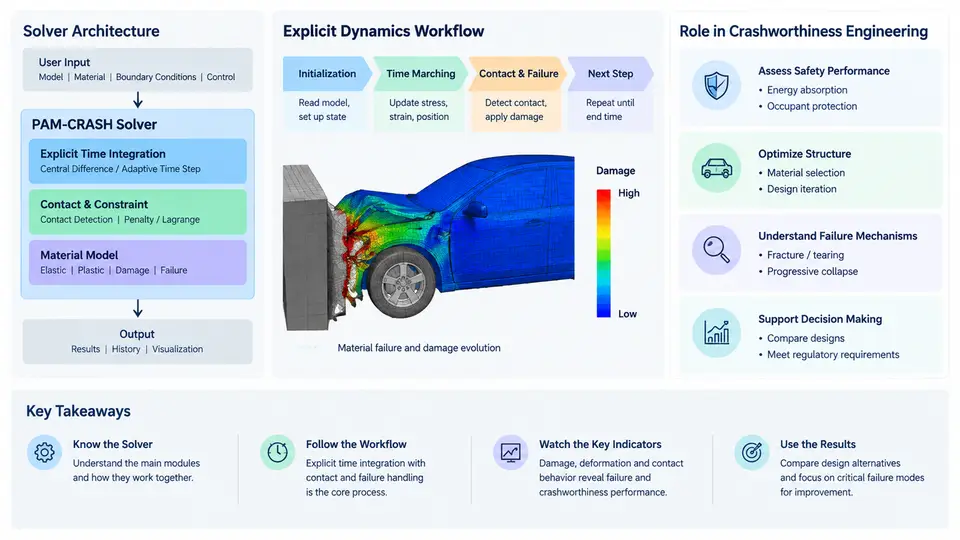
PAM-CRASH is an explicit finite element solver developed by ESI Group and widely used in the automotive and aerospace industries for crashworthiness analysis. Unlike implicit solvers that assemble and invert a global stiffness matrix at every increment, PAM-CRASH advances the solution through an explicit central-difference time integration scheme. This architectural choice has a direct consequence for material failure simulation: because no global matrix inversion is required, the solver can handle severe element distortion, contact activation and deletion, and abrupt stiffness loss caused by fracture without the convergence difficulties that plague implicit codes. Understanding this architecture is the foundation for every subsequent topic in this course, from damage model selection to element erosion criteria.
Solver Architecture and Explicit Time Integration
The explicit solver advances nodal velocities and displacements using the central-difference method. For each time step Δt, the algorithm follows a fixed sequence: compute internal forces from element stresses, apply external and contact forces, update accelerations via Newton's second law at each node, then integrate to obtain new velocities and positions. The critical time step is governed by the Courant–Friedrichs–Lewy (CFL) condition, which for a shell or solid element can be approximated as:
Δt_crit = L_e / c
c = sqrt(E / ρ)

where:
  L_e = characteristic element length
  c   = speed of sound in the material
  E   = Young's modulus
  ρ   = density
In practice, PAM-CRASH computes a per-element time step and uses the minimum across the mesh, scaled by a safety factor (default 0.9). This means a single small or highly distorted element can slow the entire simulation. Mass scaling is the standard remedy: artificially increasing the density of small elements raises their critical time step, at the cost of added kinetic energy. A common engineering guideline is to keep added mass below 1–2% of the total model mass, monitored through the GLSTAT and MASS output blocks.
Material failure and damage models interact with this architecture in two ways. First, damage evolution reduces stiffness, which lowers the local wave speed and can actually increase the stable time step — but the element is usually deleted before this becomes significant. Second, element deletion removes mass and load path from the model, which can cause a sudden drop in contact forces and a spike in kinetic energy of surrounding nodes. Monitoring these quantities is essential for judging whether a failure simulation is physically meaningful or numerically driven.
The Explicit Dynamics Workflow in Practice
A typical PAM-CRASH crashworthiness simulation with material failure follows a well-defined sequence. In the pre-processing stage, the analyst builds the mesh, assigns material cards (for example, MAT_24 for elastoplastic shells with a failure strain, or MAT_81 for a damage-mechanics-based composite model), defines contact interfaces, and applies initial velocity to the impacting structure. The initial velocity field is critical: a frontal impact simulation might use 15 m/s (54 km/h) applied to a rigid barrier or to the vehicle model, depending on the chosen reference frame.
Before the solve begins, a time-step check is mandatory. PAM-CRASH reports the minimum element time step and the corresponding element ID. If that step is below a practical threshold — for example, 1 × 10⁻⁷ s for a typical automotive mesh — the analyst must either refine the mesh locally, apply selective mass scaling to the offending elements, or accept a longer run time. The /DT/NODA and /DT/ELM options in the input deck control these settings.
During the explicit solve, the material failure logic is evaluated at every integration point of every element at every time step. For a ductile metal modeled with MAT_24, the equivalent plastic strain is compared against a failure strain ε_f. When the criterion is met, the element is deleted. For more advanced damage models such as MAT_81 or user-defined MAT_USR routines, a continuous damage variable d evolves from 0 to 1, degrading stiffness and strength progressively before final erosion. The choice between instantaneous deletion and progressive degradation depends on whether the physical failure mode is brittle (sudden) or ductile (progressive).
Practical note: Element deletion is not free. Each deleted element removes mass and load-carrying capacity. If a large cluster of elements is deleted in a single time step, the surrounding structure can experience a non-physical force spike. Monitoring the GLSTAT file for sudden jumps in kinetic energy or drops in internal energy is the standard way to detect this. A well-tuned failure simulation shows a smooth, gradual energy transfer from internal to kinetic and frictional energy.
Role in Crashworthiness Engineering
In crashworthiness engineering, the purpose of failure simulation is not merely to predict whether something breaks, but to predict how it breaks and what forces are transmitted to occupants or protected structures. PAM-CRASH is used for full-vehicle frontal, side, and rear impact simulations, occupant restraint system design, battery pack intrusion analysis for electric vehicles, and aerospace fan blade containment studies. In each case, the failure model must be calibrated against physical test data — typically a coupon test (tensile, shear, or three-point bend) — before it is trusted in a full-scale simulation.
The explicit architecture makes PAM-CRASH particularly suited to problems where failure causes topology changes: a bumper beam that fractures and separates, a spot weld that pulls out, or a composite panel that delaminates. Implicit solvers struggle with these events because the stiffness matrix becomes singular or ill-conditioned after element deletion. The explicit solver simply continues, which is both its greatest strength and its greatest risk — it will produce a result even when the result is physically meaningless. The engineer's job is to validate that result against energy balance, mass conservation, and experimental correlation.
Key takeaway: PAM-CRASH's explicit solver enables robust simulation of material failure by avoiding global matrix inversion, but this robustness demands disciplined validation. Always check the time step, monitor added mass and hourglass energy, and correlate failure predictions with coupon-level test data before applying the model to a full crash event.
Summary
This chapter established the architectural foundation for the rest of the course. PAM-CRASH uses explicit central-difference integration, which makes it naturally suited to failure and damage simulation because it tolerates element deletion and severe distortion. The workflow proceeds from pre-processing through time-step control, explicit solve, failure evaluation, and post-processing, with a feedback loop at every time step. Material failure is integrated at the constitutive level, where damage variables or failure strains trigger element erosion. The engineer's responsibility is to ensure that the simulation remains physically valid by monitoring energy balance, added mass, and correlation with experimental data. Subsequent chapters will build on this foundation, covering specific damage models, calibration procedures, and advanced techniques for composite and metallic structures.