3. Full vehicle model assembly
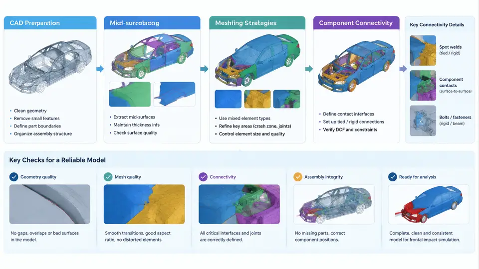
Building a full vehicle frontal impact model in PAM-CRASH is fundamentally an assembly problem. The solver itself is robust; most failed or inaccurate runs trace back to geometry that was never properly prepared, shell meshes that violate element quality limits, or connections that transfer load incorrectly. This chapter walks through the complete assembly chain — from raw CAD to a runnable, connected model — with the specific decisions that matter for a 56 km/h full frontal (or offset) impact load case.
3.1 CAD Preparation and Geometry Cleanup
Start from the BIW (body-in-white) CAD assembly plus closures (doors, hood, tailgate), powertrain, suspension, and interior subsystems. Before any meshing, the geometry must be cleaned in a CAD or pre-processor environment (ANSA, HyperMesh, or PAM-CRASH's own pre-processor). The goal is a set of surfaces that can be mid-surfaced and meshed without gaps or slivers.
Key cleanup operations, in order:
- Remove non-structural detail: delete bolt holes below ~8 mm diameter, small fillets (R < 3 mm), embosses, and trim clips. These add element count without affecting crash response.
- Heal gaps and overlaps: use "topology repair" to close free edges and stitch adjacent panels. A gap of 0.5–1.0 mm between a rail and a shotgun is normal in CAD but will produce a disconnected mesh.
- Simplify flanges: flatten complex multi-layer flanges into a single mid-surface plane where possible, but keep the flange width — it defines the spot-weld line.
- Check symmetry: for a full frontal model, exploit the vehicle's left-right symmetry. Build half, mirror, and merge — but only after confirming the load case is symmetric (full frontal is; offset deformable barrier is not).
3.2 Mid-Surfacing
Crash models are predominantly shell (2D) models. Thin-walled stamped steel — rails, pillars, floor, doors — is represented by its mid-surface, not its solid volume. Mid-surfacing extracts the neutral plane of a thin-walled part and assigns a thickness attribute.
For a typical 1.2 mm rail, the mid-surface sits 0.6 mm from each face. In practice you extract the mid-surface, then assign THICKNESS = 1.2 as a property. The critical checks after mid-surfacing:
- Thickness consistency: verify that extracted thickness matches the drawing. A rail that should be 1.6 mm but is meshed at 1.2 mm will crush too early.
- Flange alignment: mid-surfaces of two joined panels must be offset correctly so the spot-weld line lands on both. If panel A is 1.2 mm and panel B is 2.0 mm, their mid-surfaces are 1.6 mm apart — the weld must bridge that gap.
- No self-intersections: mid-surfacing often creates overlapping surfaces at corners. These must be trimmed before meshing.
3.3 Meshing Strategy
Element size is the single most important meshing decision. For frontal impact, use a graded approach:
| Zone | Target element size | Rationale |
|---|---|---|
| Front crush zone (rails, bumper, crash box) | 5 mm | Captures folding wavelength and plastic hinge formation |
| Mid-body (floor, rocker, B-pillar) | 8–10 mm | Moderate deformation, lower gradient |
| Rear / non-crush (rear rails, spare well) | 15–20 mm | Minimal deformation, save cost |
| Interior (IP, seats, trim) | 15–25 mm | Contact and inertia effects only |
Use quad-dominant meshing with a target of >95% quads in the crush zone. Triangles are acceptable in transition regions but should not exceed 5–10% locally. Maintain aspect ratio < 5, warpage < 15°, and Jacobian > 0.6. In PAM-CRASH, these map to the /QUALITY checks; run them before assembly, not after.
For the crush zone, align element edges with the expected fold lines. A rail that folds in a concertina pattern needs elements oriented perpendicular to the rail axis so the folds form cleanly. Misaligned meshes produce erratic folding and non-physical force spikes.
3.4 Component Connectivity
This is where most assembly errors occur. A full vehicle has thousands of connections: spot welds, seam welds, adhesives, bolts, and rigid links. Each type has a specific PAM-CRASH representation.
Spot welds: the dominant connection in BIW. Represent with /SPOTWELD (or a tied contact / solid element depending on fidelity). A spot weld connects two shell mid-surfaces. The weld diameter is typically 5–6 mm; model it as a single rigid or elastic-plastic beam, or as a cluster of solid elements for high-fidelity weld failure studies. For a baseline frontal model, beam spot welds with a failure criterion (e.g., force-based or plastic strain) are standard.
Seam welds and adhesives: continuous connections along flanges. Model as a row of spot welds at 20–30 mm pitch, or as a tied interface (/INTERFACE TYPE 2). Adhesive bonds in the rail flanges significantly affect crash performance and should not be omitted.
Bolted joints: suspension-to-body, powertrain mounts. Use rigid bodies (/RBODY) or tied contacts. For mounts that must fail, use a failure criterion on the rigid body or a dedicated mount element.
Rigid links: used for non-structural connections, mass attachment, and to tie subsystems. Overuse of rigid links creates artificial stiffness — use them only where the real joint is effectively rigid.
3.5 Assembly Verification
Before running the impact, perform these checks:
- Free edge check: every free edge in the model should be intentional (panel boundaries, not missed connections).
- Penetration check: run
/CHECKfor initial penetrations. Any penetration > 0.5 mm will cause an initial force spike. - Mass and CG: compare model mass and center of gravity against the physical vehicle. A 2–3% deviation is acceptable; larger indicates missing or duplicated components.
- Connectivity audit: count spot welds and compare against the weld map. Missing welds in the rail flanges are a frequent cause of premature rail separation.
3.6 Practical Notes on Model Size and Run Time
A full vehicle frontal model typically contains 1.5–3.0 million shell elements, 3,000–6,000 spot welds, and 50–150 rigid bodies. On a modern workstation (32–64 cores), a 150 ms impact simulation runs in 4–12 hours depending on element count and contact complexity. The meshing and assembly phase itself takes 2–5 days for a complete vehicle — this is normal and should be planned for.
Two cost-saving measures that do not compromise accuracy: (1) use a coarser mesh in the rear and interior, and (2) replace non-critical interior components with lumped masses attached via rigid links. Both are standard practice in production crash models.
The assembled model is now ready for the impact boundary conditions — initial velocity, barrier definition, gravity, and contact — which are covered in the next stage of the workflow.