1. PAM-CRASH solver fundamentals for crashw
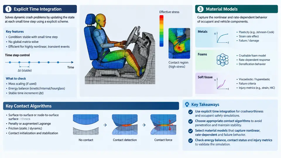
PAM-CRASH is an explicit finite element solver widely used in the automotive industry for crashworthiness simulation and occupant safety assessment. Before building a dummy model or interpreting injury criteria, you need a working mental model of how the solver advances time, how it transmits forces between bodies, and how it represents material behavior. These three pillars — explicit time integration, contact algorithms, and material models — determine whether a simulation is stable, physically meaningful, and computationally affordable.
Explicit Time Integration: The Central Difference Scheme
PAM-CRASH solves the equations of motion using an explicit central difference scheme. At each time step, nodal accelerations are computed from the assembled force vector:
M · a(t) = F_ext(t) − F_int(t)where M is the lumped mass matrix, F_ext is the external load vector (gravity, initial velocity, contact forces), and F_int is the internal force vector from element stresses. Because M is diagonal, no matrix inversion is required — accelerations are obtained by simple division. Velocities and displacements are then updated explicitly:
v(t+Δt/2) = v(t−Δt/2) + a(t) · Δt
d(t+Δt)   = d(t) + v(t+Δt/2) · Δt
The critical advantage is that each time step is cheap and no global stiffness matrix is formed. The critical disadvantage is conditional stability: the time step must satisfy the Courant–Friedrichs–Lewy (CFL) condition. For a shell element, the stable time step is approximately:
Δt_crit = L_e / cwhere L_e is the characteristic element length and c is the wave speed in the material, c = sqrt(E/ρ) for elastic solids. In practice, PAM-CRASH computes a global time step as a fraction (typically 0.9) of the minimum element time step across the model. A single distorted or tiny element can therefore dominate the cost. For occupant safety models, typical stable time steps fall in the range of 0.5–2 μs, meaning a 150 ms crash pulse requires roughly 75,000–300,000 cycles.
Contact Algorithms: Penalty and Kinematic Methods
Contact in PAM-CRASH is handled by detecting penetration between slave nodes and master segments, then applying forces to resist that penetration. The two dominant approaches are penalty-based and kinematic-based.
In the penalty method, a contact force proportional to penetration depth is applied:
F_contact = k · δwhere δ is the penetration and k is a stiffness derived from the slave and master element properties. The penalty stiffness is often scaled by a factor to balance accuracy against stability — too stiff and the time step collapses; too soft and visible penetration occurs. PAM-CRASH exposes this through contact stiffness scale factors and optional penalty stiffness control.
In the kinematic method, penetrating slave nodes are pushed back to the master surface, and momentum is conserved by distributing the correction to the master nodes. This enforces non-penetration more strictly but can introduce energy inconsistencies if not carefully controlled.
For occupant safety, the most relevant contact definitions include:
- Dummy-to-airbag contact: typically penalty-based with a soft stiffness to avoid destabilizing the inflating airbag.
- Dummy-to-seatbelt contact: often modeled with a combination of contact and belt elements, where friction coefficients (static and dynamic) control sliding.
- Dummy-to-steering-wheel or IP contact: penalty contact with thickness offsets to account for foam or trim compliance.
- Self-contact within the dummy: necessary to prevent limb interpenetration during extreme articulation.
Contact thickness is a critical parameter. Shell elements have zero physical thickness in the solver, so a contact thickness must be assigned. If the thickness is too small, the dummy may pass through the airbag; if too large, the dummy will appear to float above the surface. A common starting point is to set contact thickness equal to the physical shell thickness, then adjust based on observed penetration in the animation.
Material Models for Occupant Safety Simulation
Occupant safety simulation involves three broad material categories: metallic structures (seat frames, steering column), polymeric foams (IP padding, seat cushion), and the dummy itself (rubber, vinyl, steel). PAM-CRASH provides a library of material models, each with specific input requirements.
| Material Model | Typical Application | Key Inputs |
|---|---|---|
| Elastic-plastic (MAT 1 / MAT 10) | Steel seat frames, brackets | Young's modulus, Poisson's ratio, yield stress, hardening curve, density |
| Crushable foam (MAT 20 / MAT 50) | IP padding, seat cushion | Stress–strain curve in compression, tensile cutoff, hysteresis flag |
| Viscoelastic (MAT 6) | Dummy flesh, rubber components | Shear modulus, bulk modulus, decay constants |
| Rigid body (MAT 1 with rigid flag) | Dummy skeletal segments | Mass, inertia tensor, initial velocity |
| Airbag fabric (MAT 34 / MAT 58) | Airbag deployment | Fabric permeability, Young's modulus, damping |
For the dummy itself, the Hybrid III and THOR models distributed with PAM-CRASH use a combination of rigid bodies for skeletal segments, viscoelastic elements for flesh, and contact definitions for joints. The material parameters are calibrated against physical certification tests — for example, the Hybrid III head drop test must produce a peak resultant acceleration within a specified corridor.
Putting It Together: A Minimal Occupant Safety Load Case
Consider a simplified driver-side frontal impact model. The input deck includes:
- A rigid barrier or sled representing the vehicle deceleration pulse.
- A Hybrid III 50th percentile dummy positioned per the seating procedure.
- A seat model with foam cushion and steel frame.
- A seatbelt with retractor, slip ring, and anchor points.
- A steering wheel and column with collapsible energy-absorbing elements.
- An airbag model with inflator mass flow rate and fabric properties.
The simulation is typically run for 120–150 ms with a time step around 1 μs. Key outputs include head acceleration (for HIC), chest deflection, femur loads, and neck forces. The solver writes these to time-history files, which are then processed to compute injury criteria.
Visual Overview of the Solver Workflow
The following diagram summarizes how the three pillars interact within a single explicit time step, from force assembly through contact resolution to state update.
The loop shown above executes once per time step. In a typical occupant safety run, this loop repeats hundreds of thousands of times. Understanding each stage — and the parameters that control it — is the foundation for building reliable dummy models and interpreting injury outcomes. The next sections will build on this foundation by examining dummy positioning, belt routing, airbag interaction, and injury criteria calculation in detail.