1. Introduction to crash energy management
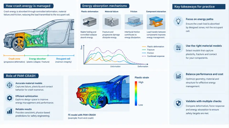
Crash energy management is the engineering discipline concerned with controlling how kinetic energy is absorbed, redirected, and dissipated during a vehicle impact event. The central objective is not to prevent deformation, but to ensure that deformation occurs in a controlled, predictable sequence that protects the occupant compartment while limiting the deceleration forces transmitted to occupants. In modern vehicle safety engineering, this discipline sits at the intersection of structural mechanics, materials science, and numerical simulation. PAM-CRASH, as an explicit finite element solver, has become one of the primary tools for evaluating and optimizing these energy management strategies before physical prototypes are built.
Fundamental Principles of Energy Management
During a collision, a moving vehicle possesses kinetic energy given by E = ½mv². For a 1,500 kg vehicle traveling at 50 km/h (13.89 m/s), the kinetic energy is approximately 144.7 kJ. This energy must be converted into other forms through structural deformation, friction, and heat. The fundamental principle of crash energy management is to distribute this energy absorption over a controlled distance and time, thereby reducing peak forces and decelerations.
Two key metrics govern occupant safety. The first is the average deceleration, which determines the forces experienced by occupants through restraint systems. The second is the peak deceleration, which must be limited to prevent injury. A well-designed crash structure maintains a relatively constant force level throughout the deformation process, avoiding sharp spikes that could cause belt loading or airbag deployment timing issues.
The concept of the "crash pulse" is central to this discussion. The crash pulse describes the deceleration-time history of the vehicle body during impact. A desirable crash pulse is characterized by a rapid rise to a controlled plateau, followed by a gradual decay. This shape ensures that the restraint system can engage the occupant early while keeping forces within tolerable limits.
Energy Absorption Mechanisms
Vehicle structures absorb energy through several distinct mechanisms, each with different force-displacement characteristics.
Progressive folding is the most common mechanism in thin-walled front rails and crash boxes. When a thin-walled column is loaded axially, it deforms in a series of local folds or "lobes." Each fold absorbs energy through plastic hinge formation. The force-displacement curve for progressive folding shows an initial peak (the buckling load), followed by a relatively stable mean crushing force. The ratio of mean crushing force to peak force is a key design parameter; a higher ratio indicates more efficient energy absorption.
Bending collapse occurs when structural members are loaded transversely. This mechanism is common in side impact and roof crush scenarios. Bending absorbs less energy per unit mass than axial folding but is often unavoidable due to geometric constraints.
Fracture and tearing can occur in high-strength materials or at high strain rates. While fracture absorbs energy, it is generally undesirable because it reduces structural integrity and can lead to unpredictable failure modes.
Friction and material damping contribute to energy dissipation through relative motion between components and through the viscoelastic behavior of materials such as polymers and adhesives.
Key design principle: The energy absorption efficiency of a structure is often expressed as the specific energy absorption (SEA), defined as the energy absorbed per unit mass of material. For automotive crash structures, typical SEA values range from 10 to 30 kJ/kg for steel and 30 to 60 kJ/kg for aluminum and composite materials.
The Role of PAM-CRASH in Vehicle Safety Engineering
PAM-CRASH is an explicit finite element solver specifically developed for crashworthiness simulation. Its core strength lies in its ability to handle large deformations, contact interactions, and material failure within a single simulation framework. The solver uses an explicit time integration scheme, which is well-suited to the highly nonlinear, transient nature of crash events.
The typical PAM-CRASH workflow for a frontal impact simulation involves several stages. First, the vehicle model is assembled from CAD geometry, with appropriate mesh density in areas expected to undergo large deformation. Shell elements are commonly used for sheet metal components, while solid elements are used for castings and thick sections. Material models are then assigned: elastoplastic models for metals, with strain-rate sensitivity included for high-strength steels, and failure criteria to capture tearing or fracture.
Boundary conditions and initial velocity are applied to represent the crash scenario. For a full frontal impact, the vehicle is typically given an initial velocity of 50 km/h against a rigid barrier. Contact definitions are established between structural components, and self-contact is defined to prevent interpenetration during folding.
The simulation output provides detailed information on deformation patterns, force-displacement curves, and energy absorption histories. Engineers use these results to identify areas of excessive intrusion, to evaluate the stability of folding patterns, and to optimize material thickness and geometry. The crash pulse extracted from the simulation is then used as input for occupant restraint system simulations, often performed in multibody or finite element occupant models.
Practical Considerations in Crash Energy Management
Effective energy management requires balancing competing requirements. A structure that is too stiff will transmit high forces to occupants, while a structure that is too soft may allow excessive intrusion into the occupant compartment. The design space is further constrained by vehicle mass, packaging requirements, and manufacturing feasibility.
In PAM-CRASH simulations, engineers typically evaluate several key outputs. The intrusion at specific measurement points (such as the brake pedal or steering column) must remain below defined thresholds. The force-displacement curve of the front structure should show a stable plateau without excessive oscillations. The energy balance must confirm that the sum of internal energy, kinetic energy, and contact energy remains consistent throughout the simulation.
A common challenge in crash simulation is achieving convergence with acceptable computational cost. The explicit time step is governed by the smallest element size and the material wave speed. For steel with a wave speed of approximately 5,000 m/s, a 5 mm element requires a time step of about 1 microsecond. A typical 100 ms crash simulation therefore requires approximately 100,000 time steps, making computational efficiency a critical consideration.
Practical tip: When setting up a PAM-CRASH crash model, always verify the initial kinetic energy against the expected value from the vehicle mass and impact velocity. A mismatch often indicates incorrect mass scaling, missing components, or unit system errors. This single check can prevent hours of debugging later.
Summary
Crash energy management is a systematic approach to controlling vehicle deformation during impact. The fundamental principles involve converting kinetic energy into controlled plastic deformation, maintaining a stable crash pulse, and protecting the occupant compartment from excessive intrusion. Energy absorption mechanisms include progressive folding, bending collapse, fracture, and friction, each with distinct force-displacement characteristics. PAM-CRASH provides a robust numerical framework for simulating these mechanisms, evaluating design alternatives, and optimizing structural performance before physical testing. The following chapters will build on these fundamentals, exploring material modeling, contact definition, and optimization strategies in greater detail.