3. Composite material modeling fundamentals
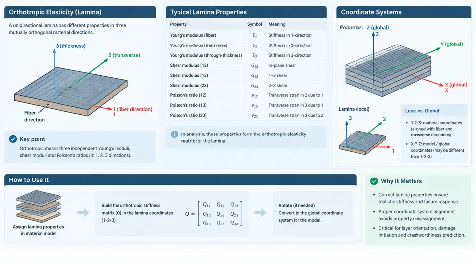
In PAM-CRASH crashworthiness simulation, the accuracy of a composite structure model depends almost entirely on how the material constitutive law is defined and how the material coordinate system is oriented relative to the structural geometry. A unidirectional carbon/epoxy lamina is not isotropic: its stiffness along the fiber direction can be more than an order of magnitude higher than transverse to the fibers. If this directionality is lost — through a misaligned material axis, a swapped modulus, or an incorrect ply angle — the simulation may still run to completion, but the predicted failure mode, energy absorption, and peak crush load will be physically meaningless. This section establishes the elasticity framework, the lamina property set, and the coordinate conventions that all subsequent composite material cards in PAM-CRASH rely on.
Orthotropic Elasticity and the Engineering Constant Set
A unidirectional lamina is treated as a transversely isotropic (a special case of orthotropic) material. Its constitutive behavior is described by Hooke's law in the material coordinate system, where the stiffness matrix contains nine independent engineering constants: three Young's moduli, three Poisson's ratios, and three shear moduli. The stress–strain relation in Voigt notation is:
{σ11}   [C11 C12 C13   0   0   0 ] {ε11}
{σ22}   [C12 C22 C23   0   0   0 ] {ε22}
{σ33} = [C13 C23 C33   0   0   0 ] {ε33}
{τ23}   [ 0   0   0  C44  0   0 ] {γ23}
{τ13}   [ 0   0   0   0  C55  0 ] {γ13}
{τ12}   [ 0   0   0   0   0  C66] {γ12}
For a plane-stress shell formulation — the typical choice for thin composite crash components in PAM-CRASH — the reduced compliance relation uses four in-plane constants: E1 (fiber-direction modulus), E2 (transverse modulus), ν12 (major Poisson's ratio), and G12 (in-plane shear modulus). The reduced stiffness terms are:
Q11 = E1 / (1 - ν12·ν21)
Q22 = E2 / (1 - ν12·ν21)
Q12 = ν12·E2 / (1 - ν12·ν21)
Q66 = G12
where ν21 = ν12 · E2 / E1
A representative T700/epoxy lamina illustrates the scale of anisotropy: E1 ≈ 135 GPa, E2 ≈ 9.5 GPa, G12 ≈ 5.0 GPa, ν12 ≈ 0.30, and density ≈ 1.55 × 10⁻⁹ t/mm³ (PAM-CRASH uses tonne–millimetre–second units). The ratio E1/E2 ≈ 14 means that a 10° fiber misalignment can shift the effective axial stiffness by several percent — enough to alter the predicted crush front progression in a composite tube.
Lamina Strength and Failure Parameters
Elastic constants alone do not define crashworthiness. The material card must also carry strength allowables that drive the failure criteria. For a typical unidirectional lamina these include:
| Parameter | Symbol | Example value | Role in PAM-CRASH |
|---|---|---|---|
| Longitudinal tensile strength | Xt | 2200 MPa | Fiber tension failure initiation |
| Longitudinal compressive strength | Xc | 1450 MPa | Fiber kinking / microbuckling |
| Transverse tensile strength | Yt | 55 MPa | Matrix cracking |
| Transverse compressive strength | Yc | 200 MPa | Matrix crushing |
| In-plane shear strength | S12 | 75 MPa | Shear-driven ply failure |
| Fracture energies | Gft, Gfc, Gmt, Gmc | 80–120 kJ/m² | Energy-based softening / element deletion |
These values are illustrative for a standard aerospace-grade carbon/epoxy and must be replaced with coupon-test data for the actual material system. The fracture energies are particularly important in crash simulation because they govern the softening slope after failure initiation and therefore the energy absorbed per unit crushed length.
Material Coordinate Systems and Ply Orientation
Every composite element in PAM-CRASH carries a local material coordinate system (1, 2, 3), where axis 1 is the fiber direction, axis 2 is transverse in-plane, and axis 3 is the through-thickness normal. The global structural coordinate system (X, Y, Z) is defined by the model. The ply angle θ is the rotation from the global X-axis to the material 1-axis, measured counterclockwise about the element normal (axis 3). This convention must be stated once and applied consistently across all plies, or the laminate will be modeled with the wrong stacking sequence.
The transformation of reduced stiffness from material axes to global axes follows the standard rotation:
Q̄11 = Q11·cos⁴θ + 2(Q12 + 2Q66)·sin²θ·cos²θ + Q22·sin⁴θ
Q̄22 = Q11·sin⁴θ + 2(Q12 + 2Q66)·sin²θ·cos²θ + Q22·cos⁴θ
Q̄12 = (Q11 + Q22 - 4Q66)·sin²θ·cos²θ + Q12·(sin⁴θ + cos⁴θ)
Q̄66 = (Q11 + Q22 - 2Q12 - 2Q66)·sin²θ·cos²θ + Q66·(sin⁴θ + cos⁴θ)
In practice, PAM-CRASH handles this transformation internally when the ply angle is supplied on the material or element card. The engineer's responsibility is to verify that the angle definition matches the intended layup. A common error is entering the ply angle as the angle from the fiber to the global axis rather than from the global axis to the fiber — a sign convention that reverses the effective stacking sequence for off-axis plies.
Laminate-Level Properties and Stacking Sequence
Real crash components use laminates, not single plies. The classical laminate theory (CLT) ABD matrix combines the ply properties and stacking sequence to give the effective in-plane, coupling, and bending stiffness. For a symmetric laminate such as [0/±45/90]s, the coupling matrix B is zero, which simplifies the response. In PAM-CRASH, the laminate is typically represented either by layered shell elements (each integration point through the thickness carries its own ply angle and material) or by a homogenized equivalent material. Layered shells are preferred for crash simulation because they capture delamination and ply-level failure, which dominate energy absorption in composite tubes and crash boxes.
The stacking sequence also determines the bending stiffness and the failure sequence. A [0/90]s laminate will fail differently from a [±45]s laminate under axial crush: the 0° plies carry the axial load and fail by fiber fracture, while the ±45° plies carry shear and fail by matrix cracking, producing a more progressive, higher-energy crush mode. The material model must therefore be paired with the correct layup definition to reproduce the intended failure mechanism.
Practical Modeling Workflow in PAM-CRASH
Translating these fundamentals into a working model follows a defined sequence. First, select the material law: for composite crash simulation, the typical choices are a ply-based progressive damage model (e.g., MAT_058 / *MAT_LAMINATED_COMPOSITE_FABRIC or the PAM-CRASH equivalent composite card) or a continuum damage model for homogenized laminates. Second, enter the elastic constants (E1, E2, G12, ν12) and strength allowables (Xt, Xc, Yt, Yc, S12) from coupon data. Third, define the ply angles and stacking sequence on the shell element property card. Fourth, assign the material orientation — either by a global angle or by a local coordinate system defined per part. Fifth, verify the fiber direction vectors visually. Sixth, run a single-element or small-panel verification case to confirm the stress–strain response before committing to a full crash model.
The coordinate system convention, the ply angle sign, and the material axis assignment are the three most common sources of error in composite crash models. Establishing them correctly at the material definition stage prevents the far more expensive mistake of debugging a full vehicle model whose energy absorption is wrong because a single ply angle was entered with the wrong sign.