1. Introduction to composite crashworthines
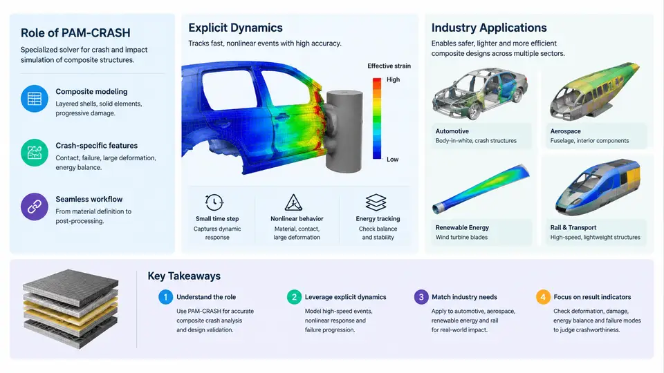
Composite structures fail in ways that metals do not. A carbon-fiber-reinforced polymer (CFRP) energy absorber does not fold into neat plastic hinges the way a steel crash box does; instead it fragments, delaminates, and crushes through a sequence of interacting damage modes — fiber microbuckling, kink-band formation, ply delamination, and matrix cracking — that unfold within milliseconds. Predicting how much energy such a structure absorbs, and whether it fails gracefully or catastrophically, is the central problem of composite crashworthiness simulation. This chapter establishes what that problem involves, why explicit dynamics is the appropriate numerical framework, where PAM-CRASH fits in the toolchain, and how the method is applied across aerospace, automotive, and rail industries.
Why Composite Crashworthiness Is a Distinct Discipline
Metallic crashworthiness rests on well-established plasticity theory. Energy absorption in a steel or aluminum structure is dominated by plastic deformation, and the material response is largely insensitive to strain rate at moderate velocities. Composite materials behave differently in three important respects.
First, their failure is brittle and progressive. A composite tube loaded in axial compression does not yield; it initiates a crush front at a trigger chamfer and then propagates that front at a roughly steady mean crush stress. The energy absorbed is the product of that stress, the crush distance, and the cross-sectional area. If the trigger is poorly designed or the layup is unfavorable, the tube may instead fail by global buckling or splitting, absorbing an order of magnitude less energy.
Second, the failure modes are strongly rate-dependent and mode-interactive. Delamination growth, matrix cracking, and fiber failure each have different rate sensitivities, and in a real crush event they couple: a delamination can trigger a kink band, which can shed load into an adjacent ply, which can then split. Capturing this coupling requires a material model that represents multiple damage mechanisms simultaneously.
Third, composite energy absorbers are highly sensitive to geometry and layup. A change in ply angle from ±45° to 0/90°, a change in wall thickness, or the addition of a chamfer trigger can shift the specific energy absorption (SEA, typically expressed in kJ/kg) by a factor of two or more. Simulation is therefore not merely a verification tool; it is a design tool used to explore that sensitivity space.
The Role of Explicit Dynamics
Crash events are short — typically 10 to 100 ms — and involve large displacements, contact, and rapidly changing stiffness as damage accumulates. An implicit solver would need to invert a global stiffness matrix at every iteration, and that matrix becomes ill-conditioned once elements degrade. Explicit dynamics avoids this entirely.
In an explicit scheme, the equations of motion are integrated directly:
M · a(t) = F_ext(t) − F_int(t)
v(t+Δt/2) = v(t−Δt/2) + a(t) · Δt
u(t+Δt) = u(t) + v(t+Δt/2) · Δt
where M is the lumped mass matrix, a is nodal acceleration, and F_ext and F_int are external and internal force vectors. Because M is diagonal, no matrix inversion is required — each nodal acceleration is computed independently. The trade-off is that the time step is bounded by the Courant–Friedrichs–Lewy (CFL) condition:
Δt ≤ L_min / c, c = sqrt(E/ρ)For a typical CFRP element with a characteristic length of 2 mm, E ≈ 60 GPa, and ρ ≈ 1600 kg/m³, the wave speed c is approximately 6100 m/s, giving a stable time step on the order of 0.3 µs. A 50 ms crush event therefore requires roughly 150,000 to 200,000 time steps. This is the fundamental computational cost of explicit crash simulation, and it is why mass scaling, subcycling, and selective element refinement are standard practice.
Where PAM-CRASH Fits
PAM-CRASH is an explicit finite element solver developed specifically for crash and impact simulation. Its relevance to composites comes from several capabilities that are not incidental but central to the workflow:
- Dedicated composite material models. PAM-CRASH provides bi-phase and multi-layer shell formulations (e.g., material law 131 for progressive ply failure) that track fiber tension, fiber compression, matrix tension, and matrix compression failure modes per ply, using Hashin-type or Puck-type criteria with energy-based softening.
- Cohesive and tie-break interfaces. Delamination is modeled either with cohesive zone elements or with tie-break contact, allowing the user to represent interlaminar fracture toughness (GIc, GIIc) explicitly.
- Robust contact. Self-contact and inter-ply contact are unavoidable once plies separate. PAM-CRASH's penalty-based contact with segment-to-segment search handles the large penetrations and sliding that occur during crush.
- Trigger and imperfection modeling. Chamfer triggers, ply-drop triggers, and geometric imperfections can be introduced directly, which is essential because a perfect cylindrical tube will not crush in a stable manner.
The solver is typically embedded in a broader workflow: geometry and layup definition in a pre-processor (ANSA, HyperMesh, or PAM-CRASH's own Visual-Environment), solving with the PAM-CRASH explicit solver, and post-processing in Visual-Viewer or a third-party tool. Material cards are calibrated against coupon tests — flat crush, open-hole compression, and mode I/II fracture tests — before being applied to a full structure.
Industry Applications
The demand for composite crashworthiness simulation comes from three sectors with different drivers.
Aerospace uses it primarily for certification. A composite fuselage section or a helicopter subfloor must demonstrate that it can absorb a specified impact energy while keeping occupant deceleration within survivable limits. The FAA and EASA accept simulation as part of the certification evidence, but only when the material models are validated against a building-block test pyramid: coupon, element, sub-component, then full article. PAM-CRASH is widely used in this pyramid because its composite material laws can be calibrated at the coupon level and then applied without re-tuning at higher levels.
Automotive uses it for lightweight body structures and battery enclosures. A CFRP front crash box or a carbon-fiber rocker panel must meet the same crash pulse targets as a steel equivalent while weighing 40–60% less. The design cycle is short, so simulation must be fast enough to evaluate dozens of layup variants. Here, PAM-CRASH's mass scaling and subcycling capabilities matter as much as its material models.
Rail and defense use it for larger structures — train cab fronts, armored vehicle floors, and blast-resistant panels — where the impact energies are higher and the loading rates span a wider range. The same explicit framework applies, but the models are larger and the contact conditions more complex.
What a First Simulation Looks Like
To make the workflow concrete, consider a simple example: a 200 mm long, 50 mm diameter CFRP tube with a 2 mm wall thickness, layup [0/±45/90]s, impacted axially at 8 m/s by a rigid mass of 200 kg. The tube is modeled with 4-node shell elements, a characteristic length of 2 mm, and material law 131 with Hashin criteria. A 45° chamfer trigger is applied at the impacted end.
The simulation is set up with a fixed time step of 0.25 µs, mass scaling applied to elements below 1.5 mm, and self-contact defined on all shell surfaces. The expected output is a crush force–displacement curve with an initial peak of roughly 60–80 kN, followed by a steady crush plateau of 35–50 kN, and a total absorbed energy of 4–6 kJ. The SEA should fall in the range of 60–90 kJ/kg for this layup. If the curve instead shows a sharp drop after the peak and a low plateau, the likely cause is insufficient trigger or a layup that promotes splitting rather than crushing — a diagnosis that the simulation itself makes visible through the damage contour plots.
Summary
Composite crashworthiness simulation sits at the intersection of explicit dynamics, damage mechanics, and structural design. PAM-CRASH provides the solver infrastructure — explicit time integration, composite material laws, cohesive interfaces, and robust contact — but the quality of the result depends on how well the material model is calibrated, how the trigger is designed, and how the energy balance is checked. The chapters that follow will build each of these elements in detail, starting with the theoretical foundations of explicit dynamics and composite damage modeling.