3. Seat CAD preparation and geometry simpli
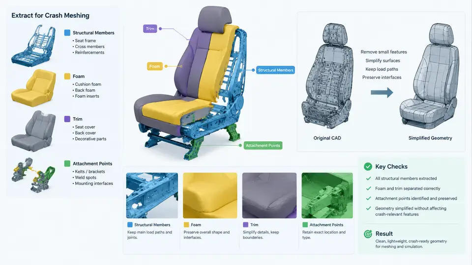
Crash meshing does not begin in the mesher — it begins in CAD. A production seat assembly delivered by the styling or BIW group typically contains hundreds of solids: stamped steel frames, welded brackets, recliner mechanisms, foam blocks, trim covers, wiring, and fasteners. Feeding that raw geometry directly into PAM-CRASH is impractical. The mesher will produce degenerate elements on fillets, the solver will waste hours on parts that carry no load, and contact definitions will become unmanageable. This chapter covers the disciplined reduction of a seat CAD assembly into a crash-ready geometry set: what to keep, what to simplify, what to delete, and how to preserve the attachment points that connect the seat to the vehicle body and to the occupant.
3.1 The Crash-Relevant Geometry Set
The first decision is scope. For a frontal sled or full-vehicle seat model, the geometry that matters falls into four functional groups:
- Structural members — seat pan, back frame, recliner, cushion frame, and mounting brackets. These carry the occupant load and must be meshed with shell elements at their true mid-surface.
- Foam — cushion and backrest padding. Foam controls occupant penetration and must be meshed as solid hexahedra with a validated material law (e.g.,
*MAT_57low-density foam or*MAT_83Fu-Chang foam). - Trim — fabric, leather, and seat covers. Trim is usually represented as a thin membrane shell with negligible stiffness, but it matters for contact friction and for foam containment.
- Attachment points — the four seat-to-floor mounts, the recliner pivot, the belt anchorages, and the head restraint posts. These are the load paths into the vehicle and must be preserved exactly.
Everything else — wiring harnesses, plastic trim clips, seat heaters, lumbar bladders, and decorative stitching — is deleted unless it carries load or defines contact. A useful rule: if a part does not appear in the load path from the occupant to the floor, and does not define a contact surface, it does not belong in the crash model.
3.2 Simplifying Structural Members
Stamped steel members are the most demanding to prepare because their CAD geometry is a thick solid with fillets, beads, and flanges. The goal is a clean mid-surface shell. The standard workflow is:
- Extract the mid-surface. Use the CAD tool's midsurface command on each sheet-metal solid. For a 1.2 mm seat pan, the mid-surface sits 0.6 mm from each face.
- Remove fillets below the mesh size. A 3 mm fillet cannot be captured by a 5 mm shell element. Suppress fillets smaller than roughly half the target element size.
- Simplify beads and stiffening ribs. Keep major beads that affect bending stiffness; remove shallow cosmetic ribs. A bead depth under 2 mm on a 1.2 mm panel contributes little to crash response.
- Repair the surface. Heal gaps, merge coincident edges, and remove sliver faces before export.
For tubular members such as the recliner shaft or head restraint posts, extract the mid-surface of the tube wall and mesh it as a shell cylinder. Do not model the tube as a solid beam unless bending collapse is the study objective.
3.3 Foam and Trim Preparation
Foam is prepared differently from steel. The cushion and backrest foam are solid volumes, and they should remain solid for hexahedral meshing. The key operations are:
- Trim the foam to the occupant contact surface. The CAD foam often extends behind the trim and into the frame. Cut it back to the surface the occupant actually contacts, plus a small margin.
- Remove internal cavities and molding features. Vent holes, wire channels, and attachment pockets are deleted unless they affect the crush mode.
- Split the foam into meshable blocks. A single complex foam solid is difficult to hex-mesh. Partition it into simple blocks along natural planes so each block can be swept or mapped.
Trim covers are extracted as surfaces offset slightly outward from the foam. They are meshed with membrane shells and assigned a low-stiffness material. The trim's main job is to provide a contact surface with the occupant and to prevent foam nodes from passing through the dummy.
3.4 Preserving Attachment Points
Attachment points are the most critical geometry in the entire seat model. If a mount is moved by even a few millimeters, the load path into the floor changes and the sled correlation will fail. Before any simplification, mark and preserve:
| Attachment | Typical Representation | Preservation Requirement |
|---|---|---|
| Seat-to-floor mounts (4x) | Rigid body or shell patch | Exact hole center and bolt diameter |
| Recliner pivot | Joint / rigid element | Pivot axis location and orientation |
| Belt anchorages | Shell patch + rigid | Anchor point coordinates per regulation |
| Head restraint posts | Shell cylinder | Post spacing and insertion depth |
Record each attachment as a named point or coordinate in a reference file. In PAM-CRASH, these become the nodes for rigid bodies, joints, and belt definitions. A common practice is to create a small coordinate table in the CAD assembly and export it alongside the geometry.
3.5 A Worked Simplification Example
Consider a driver seat with a 1.2 mm steel cushion pan, a 2.0 mm back frame, polyurethane foam, and fabric trim. The raw CAD assembly contains 214 solids. After applying the rules above:
Raw assembly:            214 solids
Deleted (wiring, clips): -96
Deleted (small fillets): -38
Merged (trim pieces):    -22
Kept structural:          18 shells
Kept foam:                 6 solids
Kept trim:                 4 membranes
Attachment points:         9 preserved
Final crash geometry:     37 parts
The simplified set is roughly one-sixth of the original part count. Mesh time drops from an estimated 14 hours to under 2 hours, and the model remains physically representative because every load path and contact surface is retained.
3.6 Geometry Quality Checks Before Meshing
Before exporting to the mesher, run a geometry audit. The checks that catch the most common failures are:
- Free edges: any shell boundary not shared by two elements. Free edges in a structural member indicate a gap that will open under load.
- Duplicate surfaces: coincident faces cause overlapping elements and contact errors.
- Normal consistency: shell normals must point consistently outward. Inconsistent normals produce wrong contact and wrong bending stiffness.
- Minimum feature size: no face smaller than half the target element size.
- Attachment point verification: confirm each preserved point still lies on the simplified geometry.
The reduction from 214 solids to 37 parts is not a loss of fidelity — it is a deliberate separation of what carries load from what does not. The structural shells, foam blocks, trim membranes, and nine attachment points together define the complete load path from the occupant through the seat into the vehicle floor. Every subsequent step in the PAM-CRASH workflow — meshing, material assignment, contact definition, and boundary conditions — depends on the quality of this geometry preparation. A clean, well-audited geometry set is the single most reliable predictor of a stable, correlatable seat crash model.