1. Automotive seat crashworthiness simulati
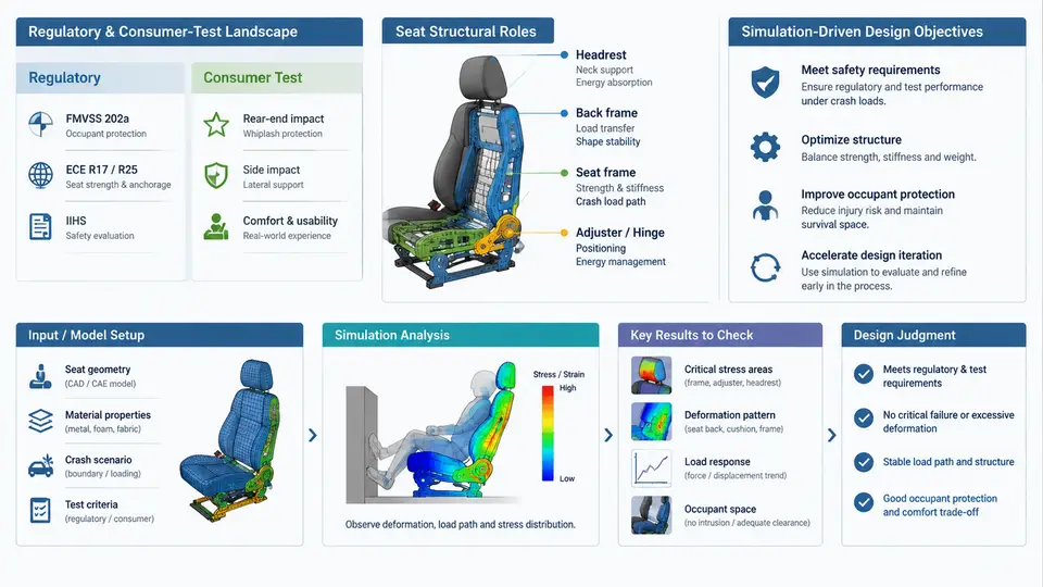
Automotive seat crashworthiness simulation sits at the intersection of occupant safety regulation, consumer rating programs, and body-structure engineering. A seat is not a passive piece of furniture: it is a load-bearing structural assembly that must survive a rear impact, restrain an occupant during a frontal crash, and provide a stable reference frame for the airbag and seatbelt systems. PAM-CRASH, with its explicit time-integration solver and extensive material and contact libraries, is widely used to predict how a seat frame, recliner, track, and foam behave under these extreme loading events. This chapter establishes the regulatory and consumer-test context, defines the structural roles of each seat subsystem, and translates those requirements into concrete simulation objectives that will drive the rest of the course.
1.1 The Regulatory and Consumer-Test Landscape
Seat crashworthiness is governed by two complementary but distinct regimes. Homologation regulations define the minimum legal requirements a vehicle must satisfy before it can be sold. Consumer-test programs go beyond the legal minimum and produce star ratings or scores that directly influence purchase decisions. A seat design that only meets the regulation may still score poorly in a consumer test, so engineers must simulate both.
The most relevant regulatory test for seat structures is ECE R17 (and its UN equivalent, UN Regulation No. 17), which covers seats, their anchorages, and head restraints. The key dynamic test is a rear-impact sled test: a sled carrying the seat and a test dummy is accelerated to a specified velocity change (Δv) and the seat must retain the dummy without catastrophic failure. ECE R17 also specifies static strength tests for the seatback and head restraint, and defines the survival space that must be preserved. In the United States, FMVSS 207 (seating systems) and FMVSS 202a (head restraints) impose analogous static and dynamic requirements, with FMVSS 202a adding a dynamic whiplash test.
Consumer programs are more demanding. Euro NCAP and China NCAP include a whiplash assessment that evaluates seat and head-restraint geometry using a BioRID II dummy in a low-speed rear impact, and a frontal offset test in which the seat must keep the occupant in the correct position for the restraint system. IIHS in the United States runs a similar rear-impact evaluation. These programs score the seat on criteria such as head-to-head-restraint contact time, neck injury criteria (NIC), and the seatback moment. The practical consequence is that a seat must be designed not only to avoid structural failure but also to control occupant kinematics within narrow corridors.
1.2 Structural Roles of the Seat Assembly
To simulate a seat correctly, you must first decompose it into the subsystems that carry load and the subsystems that control occupant motion. The following table summarizes the primary structural roles and the corresponding PAM-CRASH modelling concerns.
| Subsystem | Structural role | Dominant load case | PAM-CRASH modelling concern |
|---|---|---|---|
| Seatback frame | Transfers rear-impact moment from the occupant to the recliner and floor | Rear impact (ECE R17, whiplash) | Shell or solid elements, plastic strain at welded joints, material failure |
| Recliner mechanism | Locks the seatback angle; must not slip or fracture | Rear impact, frontal | Connector elements or detailed solid model, locking stiffness |
| Seat track and riser | Anchors the seat to the floor; carries fore-aft and vertical loads | Frontal, rear, and static strength | Spot-weld failure, bolt preload, floor deformation coupling |
| Cushion frame | Supports the occupant and distributes belt loads | Frontal offset | Contact with dummy pelvis, belt routing |
| Foam and trim | Controls occupant penetration and rebound | All dynamic cases | Low-density foam material, energy absorption, damping |
| Head restraint | Limits head rearward travel and neck rotation | Whiplash (low-speed rear) | Position, stiffness, contact with BioRID head |
Two points deserve emphasis. First, the seatback frame and recliner form the primary load path in a rear impact. The occupant's inertia generates a moment about the recliner pivot; if the recliner slips, the seatback rotates rearward and the head restraint no longer aligns with the head. Second, the seat track and floor interface is often the weak link in a frontal crash, because the seatbelt loads are transmitted through the seat structure into the floor. A simulation that models the seat in isolation, with a rigid floor, will miss the floor deformation that can rotate the seat and change belt geometry.
1.3 From Requirements to Simulation Objectives
The regulatory and consumer landscape translates into a set of simulation objectives that must be defined before any model is built. These objectives determine the load cases, the dummy models, the output requests, and the acceptance criteria.
- Predict structural integrity under rear impact. The seatback frame, recliner, and track must not fracture or permanently deform beyond the survival space. Output: plastic strain, force–displacement at the recliner, and residual seatback angle.
- Predict occupant kinematics in a whiplash test. The head must contact the head restraint early enough to limit NIC. Output: head-to-head-restraint gap, NIC time history, and head rotation angle.
- Predict seat and floor interaction in a frontal offset test. The seat must keep the occupant in position for the airbag and belt. Output: seat track displacement, belt force, and dummy chest deflection.
- Support design iteration. The model must run fast enough to evaluate multiple design variants (frame gauge, recliner stiffness, foam density) within a development cycle.
These objectives are not independent. A stiffer seatback frame improves rear-impact integrity but may increase NIC by transmitting more energy to the neck. A softer foam improves comfort but may allow excessive occupant penetration in a frontal crash. Simulation is the tool that quantifies these trade-offs before hardware is built.
1.4 A Worked Example: Rear-Impact Sled Model Setup
Consider a rear-impact sled simulation of a front seat using PAM-CRASH. The input deck is organized around the following example parameters, which are representative of a mid-size passenger car seat and are provided here as a teaching example, not as measured data.
# Example PAM-CRASH input structure (illustrative)
# Units: mm, ms, kg, kN
*CONTROL
  TEND = 120.0        # termination time [ms]
  DTINIT = 1.0e-3     # initial time step [ms]
  DTSCALE = 0.9       # time-step scale factor
*MATERIAL
  # Seatback frame: high-strength steel
  MAT_ELASTIC_PLASTIC  ID=10  RHO=7.85e-9  E=210.0  NU=0.3  SIGY=0.35
  # Foam: low-density polyurethane
  MAT_LOW_DENSITY_FOAM ID=20  RHO=5.0e-11  E=0.05  SIGY=0.002
*SECTION_SHELL
  ID=100  T=1.2       # seatback frame thickness [mm]
*PART
  ID=1  SECID=100  MID=10   # seatback frame
  ID=2  SECID=200  MID=20   # cushion foam
*CONTACT
  # Dummy-to-seat contact
  CONTACT_AUTOMATIC_SURFACE_TO_SURFACE
  SLAVE=DUMMY  MASTER=SEAT  MU=0.3
*BOUNDARY
  # Sled acceleration pulse applied to floor nodes
  PRESCRIBED_ACCELERATION  NODE_SET=FLOOR  LCID=500
*DATABASE
  # Output requests
  NODOUT  NODE_SET=HEAD  DT=0.5
  ELOUT   PART_SET=SEATBACK  DT=0.5
The sled pulse is defined as a time–acceleration curve (LCID 500) that reproduces the Δv of the regulatory test. For ECE R17, the example pulse reaches approximately 20 g over 50 ms, giving a Δv of about 30 km/h. The dummy model (BioRID II or Hybrid III, depending on the test) is positioned in the seat with the head restraint at the design position.
After the run, the engineer inspects three things. First, the seatback rotation: if the recliner slips, the seatback angle increases rapidly and the head restraint moves away from the head. Second, the plastic strain in the seatback frame: values above the material's failure strain indicate a potential fracture. Third, the NIC from the dummy neck: a peak above the consumer-test threshold indicates a whiplash problem. If the seatback rotates too far, the typical fix is to increase the recliner locking stiffness or add a reinforcement bracket; if NIC is too high, the head restraint is moved closer to the head or the foam is stiffened.
1.5 Visual Overview of the Seat Load Path and Simulation Workflow
The following diagram summarizes how the regulatory and consumer requirements map onto the seat structure and the simulation workflow. It shows the two primary load paths (rear impact through the seatback and recliner, frontal impact through the track and floor) and the corresponding PAM-CRASH model outputs that must be checked.
The diagram makes the two load paths explicit. In a rear impact, the occupant's inertia loads the seatback frame, which transfers the moment to the recliner and then to the floor. The critical simulation outputs are the seatback rotation and the plastic strain in the frame. In a frontal offset, the belt load is transmitted through the seat track into the floor; the critical outputs are the track displacement and the resulting change in belt geometry. A complete seat model must include both paths, because a design change that helps one may hurt the other.
1.6 Summary and Design Objectives
This chapter has established the context for the rest of the course. The regulatory landscape (ECE R17, FMVSS 207, FMVSS 202a) defines the legal minimum, while consumer programs (Euro NCAP, China NCAP, IIHS) define the market expectation. The seat structure decomposes into load-bearing subsystems (seatback frame, recliner, track, cushion frame) and occupant-interaction subsystems (foam, trim, head restraint). Each subsystem has a dominant load case and a corresponding PAM-CRASH modelling concern.
The simulation objectives that follow from this context are: predict structural integrity under rear impact, predict occupant kinematics in a whiplash test, predict seat–floor interaction in a frontal offset, and support rapid design iteration. These objectives will be revisited in every subsequent chapter, because they determine what the model must capture, what outputs must be requested, and how the results must be judged. The next step is to build the seat model itself, starting with the geometry, mesh, and material definitions that make these predictions possible.