1. Introduction to PAM-CRASH in automotive
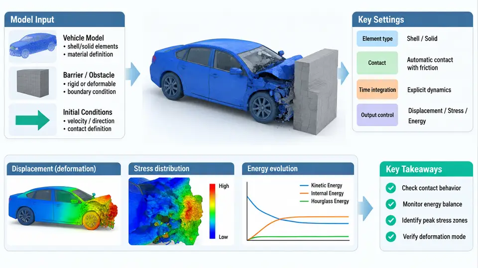
PAM-CRASH is an explicit finite element (FE) solver purpose-built for the simulation of highly nonlinear, transient dynamic events — most notably vehicle crashworthiness. Unlike implicit solvers that assemble and invert a global stiffness matrix at every load step, PAM-CRASH advances the solution through an explicit central-difference time integration scheme. This architectural choice is what makes it possible to resolve contact, large deformation, material failure, and self-contact of a full vehicle body-in-white (BIW) within a practical turnaround time.
Why Explicit Integration Dominates Crash Analysis
The governing equation solved at each increment is Newton's second law written in discretized form:
M · a(t) = F_ext(t) − F_int(t) + F_contact(t)where M is the lumped (diagonal) mass matrix, a is nodal acceleration, F_ext is the applied external load, F_int is the internal element force, and F_contact is the contact interface force. Because M is diagonal, no matrix inversion is required — nodal accelerations are obtained by simple division, and velocities and displacements follow by explicit central-difference updates. The critical consequence is that each increment is computationally cheap, but the scheme is only conditionally stable: the time step must satisfy the Courant–Friedrichs–Lewy (CFL) condition.
Δt ≤ Δt_crit = 2 / ω_max ≈ L_min / cHere L_min is the smallest element characteristic length and c is the dilatational wave speed in the material. For a typical steel shell element of 5 mm edge length with c ≈ 5000 m/s, Δt_crit is on the order of 1 µs. A 150 ms frontal impact therefore requires roughly 150,000 increments — which is precisely why mass scaling, selective sub-cycling, and shell-element dominance are standard practice in crash models.
Solver Architecture and the Crash Workflow
PAM-CRASH is not a single monolithic program. It is a solver core surrounded by a preprocessing and postprocessing ecosystem. The pamcrash solver executable reads a keyword-driven input deck (historically .pc / .dsy format, now also supporting LS-DYNA-style keyword decks), performs the explicit time integration, and writes time-history and state data to result files. The Visual-Crash PAM (VCP) environment handles model assembly, keyword editing, and result animation.
The architecture can be understood as four cooperating layers: the model definition layer (nodes, shell/solid elements, materials, connections), the contact and constraint layer (self-contact, tied interfaces, rigid walls, spotwelds), the time integration core (explicit central difference with CFL control), and the output layer (d3plot-equivalent animation, nodal time history, section forces). Understanding this separation is essential because most solver failures — negative volume, excessive mass scaling, contact penetration — originate in the model definition or contact layer, not in the integration core itself.
Role in Vehicle Safety Development
In a modern OEM development program, PAM-CRASH sits at the center of the CAE-driven safety process. A typical full-vehicle frontal offset deformable barrier (ODB) model contains 1.5–3 million shell elements, 200–500 rigid bodies, and several thousand spotwelds. The simulation must reproduce the Euro NCAP or FMVSS 208 load case within a correlation tolerance of roughly ±10% on occupant compartment intrusion and deceleration pulse.
The practical value of the explicit approach becomes clear when you consider what the solver must capture simultaneously: sheet metal folding and tearing, weld nugget failure, airbag deployment (via FPM or ALE coupling), seatbelt pretensioner firing, and occupant kinematics through a multi-body or FE dummy. Each of these is a distinct nonlinearity, and the explicit scheme handles them without the convergence difficulties that plague implicit solvers on contact-dominated problems.
Practical Example: Setting Up a Frontal Impact Run
Consider a simplified full-vehicle frontal rigid-wall impact. The essential inputs are:
- Initial velocity: 50 km/h (13.89 m/s) applied to all nodes in the −X direction (vehicle forward axis defined as +X, so the barrier is at −X).
- Barrier: rigid wall with a 1000 kg added mass, positioned 50 mm from the front bumper.
- Termination time: 120 ms, with output every 1.5 ms.
- Time step control: initial
Δt = 1.2e-6 s, with mass scaling limited to a 5% added-mass ceiling.
After the run, the first checks are the energy balance (kinetic + internal + contact + hourglass should equal initial kinetic within 2%) and the added-mass percentage. If the hourglass energy exceeds 5% of internal energy, the shell formulation or element quality needs attention. If contact penetration exceeds the shell thickness, the penalty stiffness or contact thickness must be adjusted.
What This Course Covers
Over the following chapters, you will move from this architectural overview into the concrete mechanics of building, running, and validating PAM-CRASH models. The emphasis throughout is on the decisions that determine whether a simulation is predictive: element formulation and mesh quality, material card selection, contact parameter tuning, and the interpretation of results against physical test data. The explicit solver is a powerful instrument, but its output is only as trustworthy as the engineering judgment applied to its inputs.