1. Airbag system fundamentals for PAM-CRASH
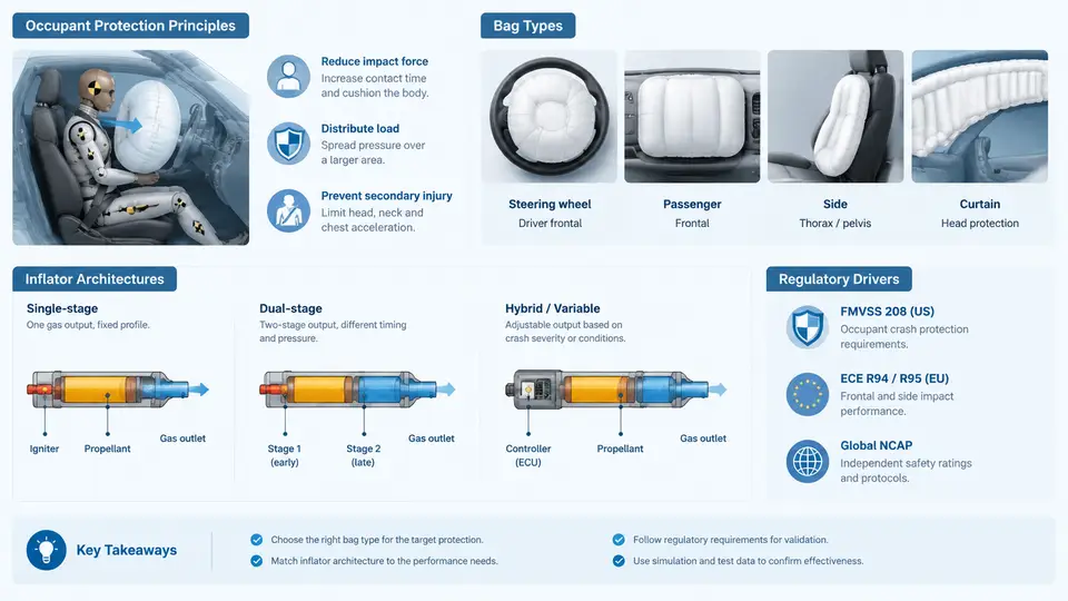
Before a single finite element is meshed, the analyst must understand what the airbag system is actually supposed to do, how its hardware behaves, and which regulatory or consumer-test requirements the simulation will ultimately be judged against. In PAM-CRASH workflows, the airbag is not a decorative add-on to the occupant model — it is a coupled fluid-structure system whose internal pressure, venting, and fabric kinematics determine the restraint forces transmitted to the dummy. This chapter establishes the physical and regulatory foundation that every later modeling decision depends on.
Occupant Protection Principles
An airbag does not "cushion" an occupant in the everyday sense. Its primary function is to manage the deceleration of the occupant's head and torso by distributing restraint load over a large area and over a longer time interval than a hard surface contact would allow. The physical quantity that matters is the occupant's kinetic energy, E = ½mv², which must be dissipated through controlled deformation of the bag, venting of inflation gas, and interaction with the seat belt and steering column or instrument panel.
Three principles govern the design:
- Timing. The bag must be fully deployed before the occupant's head reaches the region it protects. In a 50 km/h frontal barrier test, the occupant begins moving forward roughly 30–50 ms after impact, so the inflator must complete filling within approximately 20–30 ms.
- Pressure management. Internal bag pressure must be high enough to arrest the head but low enough to avoid excessive rebound or neck injury. This balance is achieved through vent holes, fabric permeability, and inflator output tuning.
- Load distribution. The bag spreads contact force across the head and chest, reducing peak pressure on any single anatomical region. This is why bag geometry and fold pattern matter as much as inflator size.
In PAM-CRASH, these principles translate directly into model inputs: the *AIRBAG definition controls gas mass flow rate, the vent area and discharge coefficient control pressure decay, and the fabric material law controls how the bag stretches and wrinkles during contact.
Bag Types and Their Modeling Implications
Different bag architectures impose different modeling requirements. The table below summarizes the most common types encountered in PAM-CRASH projects.
| Bag Type | Typical Application | Key Modeling Consideration |
|---|---|---|
| Driver frontal (DAB) | Steering-wheel-mounted, 50–70 L | Circular fold pattern; strong interaction with steering column stroke |
| Passenger frontal (PAB) | Instrument-panel-mounted, 80–120 L | Large volume; seam and tether layout dominate deployment shape |
| Side torso (SAB) | Seat-mounted or door-mounted, 12–20 L | Fast fill time (10–15 ms); close proximity to occupant |
| Curtain (CAB) | Roof-rail-mounted, 20–40 L | Elongated geometry; coverage of side windows and pillars |
| Knee (KAB) | Lower instrument panel, 15–25 L | Load path through femur; interaction with knee bolster |
Each type requires a different combination of *AIRBAG reference geometry, fold definition, and inflator characteristic curve. A curtain bag, for example, cannot be modeled with the same uniform-pressure assumption that works for a driver bag, because its elongated shape produces significant pressure gradients along its length.
Inflator Architectures
The inflator is the energy source. Its output curve — mass flow rate versus time — is the single most important input to the airbag model. Three architectures dominate:
- Pyrotechnic. A solid propellant burns to generate gas. Fast, compact, and high-temperature. The mass flow curve rises sharply and decays over 20–40 ms. In PAM-CRASH, this is defined as a time-dependent mass flow rate table.
- Hybrid. A small pyrotechnic charge heats stored compressed gas (argon/helium). The result is a more controllable pressure profile and lower peak temperature. The mass flow curve is smoother and often includes a sustained plateau.
- Cold gas / stored gas. Used mainly in side bags and some curtain systems. No combustion; gas is released from a pressurized vessel. The flow curve is nearly rectangular, with a sharp onset and rapid decay once the vessel pressure drops.
For PAM-CRASH, the inflator is represented by a *AIRBAG card referencing a mass flow rate table and a gas mixture definition. The gas mixture specifies the ratio of specific heats (γ) and the gas constant (R), which control the pressure-temperature relationship inside the bag. A typical hybrid inflator for a driver bag might use a 70% argon / 30% helium mixture with γ ≈ 1.67 and R ≈ 280 J/(kg·K). These values are example assumptions for teaching purposes; actual inflator data must come from supplier-provided tank test curves.
Regulatory and Consumer-Test Drivers
Simulation results are ultimately compared against regulatory and consumer-test criteria. The most relevant for frontal airbag validation are:
- FMVSS 208 (US): specifies unbelted and belted frontal barrier tests at 25–35 mph, with HIC ≤ 700, chest deflection ≤ 63 mm, and femur load ≤ 10 kN for the 50th-percentile male dummy.
- ECE R94 (Europe): similar barrier tests but with different dummy positioning and a focus on belted occupants; HIC ≤ 1000 and chest deflection ≤ 75 mm.
- Euro NCAP: consumer rating that adds offset deformable barrier (ODB) tests at 64 km/h and evaluates head, chest, and knee injury criteria with stricter thresholds than regulation.
- C-NCAP: similar to Euro NCAP but with a 50 km/h full frontal rigid barrier and a 64 km/h ODB test; HIC ≤ 700 for a 5-star rating.
These criteria define the target metrics that the PAM-CRASH model must reproduce. If the simulation predicts HIC = 650 but the physical test measures 720, the model is not validated — regardless of how visually convincing the deployment animation looks.
From Physics to Simulation: The Coupling Chain
The diagram below shows how the physical airbag system maps onto PAM-CRASH model entities. The inflator provides mass flow and gas properties; the bag fabric provides the structural boundary; the vent and leakage paths control pressure decay; and the occupant dummy provides the contact interface. Each link in this chain must be defined consistently for the simulation to be predictive.
The feedback loop shown on the right side of the diagram is critical: as the bag inflates, the internal pressure acts on the fabric, which deforms and changes the bag volume. That volume change, in turn, affects the pressure through the ideal gas relation P·V = m·R·T. PAM-CRASH solves this coupling at each time step using a control-volume approach, where the bag is treated as a chamber with uniform or zone-wise pressure. The accuracy of this coupling depends on the gas mixture properties and the vent discharge coefficient — both of which must be calibrated against physical tank tests or sled tests before the model can be considered validated.
With this foundation — protection principles, bag types, inflator architectures, and regulatory targets — the next step is to translate the physical system into a working PAM-CRASH model. That translation begins with the *AIRBAG keyword and the reference geometry that defines the bag's initial shape and fold pattern.