3. MADYMO modeling environment
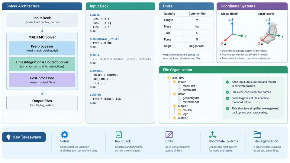
Before a single restraint parameter can be correlated against a physical sled test, the analyst must be fluent in the environment that executes the simulation. MADYMO (Mathematical Dynamic Model) is a rigid-body-plus-finite-element multibody solver whose sled workflow is governed by a small set of architectural rules: how the solver is structured, how the input deck is organized, which unit system is active, how coordinate frames are defined, and how files are laid out on disk. Getting any one of these wrong produces results that look plausible but are physically meaningless — a classic correlation failure that is often misattributed to the model rather than the setup.
Solver Architecture
MADYMO separates the problem into a multibody (MB) system and a finite element (FE) system, coupled through a shared time-integration loop. The MB solver handles rigid bodies, joints, and kinematic constraints using a recursive formulation; the FE solver handles deformable structures (airbags, belts, seats, dummy flesh) using explicit time integration. In a sled reconstruction, the typical split is:
- MB domain: the sled buck, seat frame, dummy rigid segments, belt retractor and pretensioner kinematics, and joint stops.
- FE domain: the airbag fabric and gas flow, the belt webbing, the seat cushion foam, and any deformable contact surfaces.
- Coupling: MB-to-FE and FE-to-MB contact interfaces, plus the
SYSTEM.MB/SYSTEM.FEswitches that activate each domain.
The solver reads a single input deck, builds the model, and advances the solution with a fixed or adaptive time step. For sled work, the time step is usually governed by the FE domain (fabric and foam elements), so the MB domain is sub-cycled. The analyst must therefore check the TIME_STEP and COUPLING settings before trusting any acceleration trace.
Input Deck Structure
A MADYMO input deck is a plain-text file organized into data blocks, each introduced by a keyword and terminated by the next keyword. The order is not arbitrary: the solver builds the model in the sequence it reads. A minimal sled deck follows this skeleton:
SYSTEM.MB
  MB_BODY / 1, 0.0, 0.0, 0.0
  MB_JOINT / ...
SYSTEM.FE
  FE_MODEL / ...
SYSTEM.COUPLING
  MB_FE_CONTACT / ...
TIME_STEP / 1.0E-6
TIME_END / 0.150
OUTPUT / ...
Each block contains cards (also called data lines) with comma-separated fields. Field order is fixed by the card definition; a misplaced comma shifts every subsequent value. The most common deck-level errors in sled models are:
- Missing
SYSTEM.FEblock when an airbag is referenced — the solver silently ignores the FE part. - Wrong
TIME_END(e.g., 0.150 s instead of 0.150 s of physical time, but written as 150 ms in a field expecting seconds). - Output requests placed before the model is fully defined, producing empty result files.
Units
MADYMO does not enforce a unit system; it enforces consistency. The analyst declares units implicitly through the numbers entered. The two common systems in sled work are:
| Quantity | SI (recommended) | Legacy mm-t-s |
|---|---|---|
| Length | m | mm |
| Mass | kg | tonne (103 kg) |
| Time | s | s |
| Force | N | N |
| Acceleration | m/s2 | mm/s2 |
Mixing systems is the single most frequent cause of a model that "runs but is wrong." A belt force entered in N while the geometry is in mm will produce a stiffness three orders of magnitude too low. The practical rule: pick SI, write it at the top of the deck as a comment, and convert every input from the test data sheet before entry. Sled acceleration pulses from the test lab are usually in g; convert to m/s2 by multiplying by 9.81.
Coordinate Systems
MADYMO uses a right-handed Cartesian system. The global frame is defined by the analyst; the local frames are attached to bodies and joints. For sled simulations, the convention that matches most test labs is:
- X: longitudinal, positive forward (direction of travel).
- Y: lateral, positive to the driver's left.
- Z: vertical, positive upward.
Rotations follow the right-hand rule about each axis. The sled pulse is applied as a prescribed acceleration on the buck body, typically along +X (deceleration is negative X). The dummy is positioned relative to the buck using local frames; the H-point and the seat back angle are the two reference measurements that must match the test setup. A mismatch of even 10 mm in H-point location changes belt geometry and invalidates the correlation.
When a local frame is defined, the analyst must state its origin and orientation explicitly. MADYMO does not infer orientation from geometry. The MB_BODY card takes position and orientation as separate fields; swapping them is a common error that produces a body at the right place but rotated 90°.
File Organization
A sled reconstruction is rarely a single file. The practical layout separates input, includes, output, and post-processing so that a parameter change does not require editing the entire deck. The recommended structure is:
sled_case/
  input/
    main.dat          # SYSTEM, TIME, OUTPUT blocks
    airbag.dat        # FE airbag model
    belt.dat          # belt and retractor definition
  include/
    units.inc         # unit declaration comment + conversion factors
    frames.inc        # global and local frame definitions
  output/
    run_001.out
    run_001.kn3
  post/
    test_pulse.csv
    correlation.xlsx
The include/ directory is the key to reproducibility. By placing the unit declaration and the frame definitions in shared include files, every run in the project uses the same conventions. When a correlation fails, the first check is whether the include files were modified between runs.
Practical Verification Before Running
Before submitting a sled deck, perform these checks in order:
- Unit audit: confirm every length is in m, every mass in kg, every force in N. Convert the test pulse from g to m/s2.
- Frame audit: confirm the global frame matches the test lab convention (+X forward, +Z up, +Y left). Confirm the dummy H-point and seat back angle match the test setup.
- Deck audit: confirm
SYSTEM.MB,SYSTEM.FE, andSYSTEM.COUPLINGare all present and in the correct order. - Time audit: confirm
TIME_ENDcovers the full event (typically 0.120–0.150 s for a frontal sled) andTIME_STEPis stable for the smallest FE element. - Output audit: confirm the requested output channels include sled acceleration, belt force, and dummy head/chest accelerations — the three signals used for correlation.
Mastering this environment is not about memorizing keywords; it is about internalizing the constraints that make a sled model physically meaningful. The solver architecture determines what can be coupled, the input deck determines what is built, the units determine whether the numbers are real, the coordinate frames determine whether the geometry is correct, and the file organization determines whether the work is reproducible. Each of these is a prerequisite for the correlation work that follows.