1. Side impact occupant safety simulation w
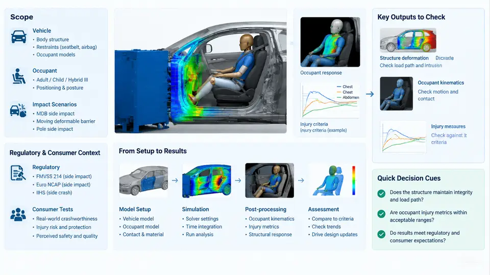
Side impact remains one of the most demanding load cases in occupant safety engineering. The struck vehicle has very little crush space between the striking barrier and the occupant, the door trim and armrest intrude directly into the occupant's survival space, and the time available for restraint deployment is measured in tens of milliseconds. MADYMO — the Mathematical Dynamic Model, now distributed within the TASS International / Siemens Simcenter portfolio — has been the reference tool for this problem for more than three decades, precisely because it combines multibody (MB) dynamics for fast restraint-system iteration with finite element (FE) capability for deformable contact surfaces such as door trim, armrests, and side airbags.
This chapter establishes the scope of the course, the regulatory and consumer-test landscape that defines the targets, and the end-to-end simulation workflow that every later chapter refines. It is deliberately a map, not a manual: the goal is that after reading it you can place any subsequent technique — a facet-surface door model, an ES-2re dummy, a pole test setup — into a coherent process.
Why MADYMO for Side Impact
Three properties make MADYMO particularly well suited to lateral loading:
- Hybrid MB/FE modelling. The occupant can be represented as a multibody system (rigid bodies connected by kinematic joints and force models), while the intruding door, armrest, and side airbag are represented as FE meshes. Contact between the two is handled by MADYMO's own contact algorithms, so the dummy does not need to be meshed.
- Computational cost. A typical MB dummy against an FE door runs in minutes rather than hours, which makes design-of-experiments studies over airbag pressure, trim stiffness, and seat position practical.
- Validated dummy models. MADYMO ships with correlated ES-2, ES-2re, EuroSID-2, SID-IIs, WorldSID 50th, and Q-series child models, each with documented certification corridors.
The trade-off is that the vehicle structure itself is usually not modelled in MADYMO. Instead, the door intrusion and vehicle deceleration are imported from a full-vehicle FE simulation (typically LS-DYNA or PAM-CRASH) or from a physical sled test. This decoupling is the single most important architectural decision in a MADYMO side impact study, and it is revisited in Chapter 4.
Regulatory and Consumer-Test Context
Side impact targets come from two families of tests, and they differ in barrier, dummy, impact angle, and injury criterion. The table below summarises the principal cases a MADYMO model is normally required to reproduce.
| Test | Barrier / Geometry | Dummy | Primary Criteria |
|---|---|---|---|
| FMVSS 214 (US, dynamic) | MDB, 27° crab, 54 km/h | ES-2re (driver), SID-IIs (rear) | Rib deflection, TTI(d), pelvic acceleration |
| ECE R95 / UN R95 | MDB, 90°, 50 km/h | EuroSID-2 | Rib deflection, abdominal force, pubic symphysis force |
| Euro NCAP side mobile barrier | AE-MDB, 60 km/h | WorldSID 50th | Rib deflection, abdominal pressure, pelvic force |
| Euro NCAP oblique pole | Rigid pole, 32 km/h, 75° | WorldSID 50th | Head, thorax, abdomen, pelvis |
| IIHS side (updated) | MDB, 60 km/h, 2,190 kg | SID-IIs | Head, torso, pelvis injury measures |
Two practical consequences follow. First, the same vehicle must usually be evaluated with more than one dummy and more than one barrier, so the model architecture must be parameterised rather than hard-coded. Second, the injury criteria are measured at specific locations — rib deflection is read from the dummy's internal displacement transducers, not from the outer surface — so the dummy model's instrumentation channels must be mapped correctly to the output requests.
The End-to-End Workflow
A complete MADYMO side impact study moves through six stages. The figure below shows the data flow between them, including the external inputs that come from full-vehicle FE or physical testing.
Each stage has a concrete deliverable and a concrete failure mode:
- Model setup. Assemble the dummy (e.g.
ES2RE_V1.0orWORLDSID_50F_V3.0), the seat, the door trim, and the side airbag into a single MADYMO input deck. The dummy is placed in the vehicle reference frame using the H-point and the seat-back angle from the CAD package. A common error here is a mismatch between the dummy's pelvis origin and the seat H-point, which shifts every subsequent injury reading. - Positioning. Adjust joint angles to the posture specified by the test procedure — for FMVSS 214 the ES-2re is positioned with the seat at the design position and the dummy's feet on the floorpan; for Euro NCAP the WorldSID is positioned per the latest protocol. Positioning is done with MADYMO's
INITIAL.JOINTandINITIAL.FREE_JOINTcards, and the resulting joint angles should be logged for traceability. - Loading. Apply the door intrusion as a prescribed motion to the FE door mesh, and apply the vehicle deceleration pulse to the seat and floor. The intrusion curve is typically a time-history of nodal displacement extracted from the full-vehicle FE run at the door inner panel.
- Simulation. Run the coupled MB/FE simulation. Typical side impact events are 120–150 ms; a stable timestep for the FE door is on the order of 1 µs, so the run is usually executed with MADYMO's explicit solver.
- Post-processing. Extract rib deflections, abdominal forces, pelvic accelerations, and head accelerations from the dummy's instrumentation channels. Convert accelerations to HIC or 3 ms clip values where required.
- Assessment. Compare each value against the regulatory or consumer-test limit. If a limit is exceeded, the iteration loop returns to stage 1 or 2 — usually to adjust airbag pressure, trim stiffness, or seat position.
What This Course Covers
The remaining chapters follow the workflow above in order, but each chapter is self-contained. Chapters 2–3 cover dummy selection and the regulatory/consumer-test matrix in detail. Chapters 4–6 cover model assembly, positioning, and the import of FE intrusion data. Chapters 7–12 cover restraint modelling — side airbags, curtain airbags, door trim, and seat structures. Chapters 13–20 cover simulation execution, contact definition, and solver settings. Chapters 21–27 cover post-processing, injury criteria calculation, and correlation against physical test data. Chapters 28–30 cover design-of-experiments, automation, and reporting.
By the end of the course you should be able to build a MADYMO side impact model from a CAD package and a full-vehicle FE result, run it, extract the injury criteria, and judge whether the design meets its targets — and, when it does not, know which parameter to change first.