3. MADYMO model setup for restraint validat
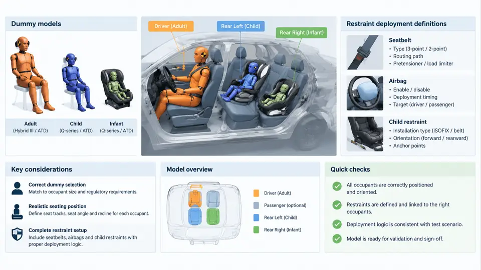
Once the validation matrix and load cases are fixed, the credibility of every subsequent result depends on how faithfully the MADYMO model reproduces three things: the occupant (dummy model), where that occupant sits (seating position), and how the restraint hardware behaves (deployment definition). A restraint sign-off is only as trustworthy as these three pillars. This section walks through how each is built in practice, using a driver-side frontal airbag plus seat-belt case as the running example.
Dummy models: choosing the right occupant representation
MADYMO ships with a family of validated dummy models — Hybrid III 50th, Hybrid III 5th, THOR 50th, Q-series child dummies, and the BioRID rear-impact dummy. The choice is driven by the regulation or consumer protocol being signed off, not by convenience. FMVSS 208 frontal occupant protection, for example, mandates the Hybrid III 50th percentile male; Euro NCAP frontal MPDB uses both the Hybrid III 50th and the THOR 50th; child occupant protection uses Q3, Q6, and Q10.
Each dummy is a multi-body system of rigid bodies connected by joints with defined stiffness and damping. The critical setup parameters are:
- Mass and inertia distribution — must match the physical dummy certification values. A 50th percentile Hybrid III head weighs approximately 4.54 kg; if the model's head mass is edited without re-certifying the neck response, head injury criteria (HIC) results become meaningless.
- Joint characteristics — neck, lumbar spine, and knee slider stiffness curves are supplied as
CHARACTERISTICtables in the dummy's.xmlinclude file. These should never be hand-tuned to make a result pass. - Contact definitions — the dummy's outer surfaces (head, chest, pelvis, knees) are defined as ellipsoids or facet surfaces. Contact stiffness between dummy and airbag, dummy and belt, and dummy and interior trim must be declared explicitly.
A common failure mode is a dummy that "floats" through the airbag because the contact thickness was set too small, or one that penetrates the seat because the seat contact was omitted. Always verify contact by running a short settling simulation and checking that the dummy rests on the seat cushion with the expected pelvis angle (typically 20–25° for a Hybrid III 50th in a standard seating buck).
Seating positions: from nominal to worst-case
The nominal seating position is defined by the H-point, seat back angle, and cushion angle taken from the CAD seat model. But restraint validation rarely stops at nominal. The model must be able to place the dummy at the positions that the regulation or protocol specifies:
| Position | Typical definition | Why it matters |
|---|---|---|
| Nominal (design H-point) | H-point at CAD position, seat back at design angle | Baseline performance reference |
| Forward-most | Seat track full forward, seat back upright | Out-of-position (OOP) airbag interaction |
| Rearward-most | Seat track full rearward, seat back reclined | Belt geometry and airbag reach |
| Reclined | Seat back at maximum recline angle | Submarining risk, belt fit |
In MADYMO, the seating position is controlled by the INITIAL.JOINT and INITIAL.FREE_BODY entries, or more commonly by a SYSTEM.SEAT model with a defined H-point and a POSITION keyword. The dummy is placed by specifying the pelvis position and orientation, then the joint angles are set to achieve the target posture. A practical approach is to define the seat as a separate system, position the dummy relative to the seat's H-point, and then apply a settling phase (typically 50–100 ms of gravity) so the dummy settles naturally onto the cushion before the impact pulse begins.
Restraint deployment definitions
Restraint deployment is where the model becomes a system rather than a collection of parts. Three elements must be defined: the belt, the airbag, and their timing.
Seat belt. The belt is modeled as a BELT system with a FE_MODEL or multi-body belt segments. Key inputs are the belt path (defined by BELT.ANCHOR and BELT.SLIP_RING points), the belt stiffness (force–strain curve from the webbing supplier), the pretensioner stroke and force, and the load limiter force level. A typical pretensioner might pull 60–80 mm of webbing with a peak force of 2–3 kN, while a load limiter holds belt force at 4–6 kN. These values must come from component test data, not from guesswork.
Airbag. The airbag is defined by its folded geometry, its GAS_FLOW model (either a uniform pressure model or a more detailed GAS_PARTICLE / GAS_FULL model), and its venting. The uniform pressure model is adequate for most frontal driver airbags; the particle model is needed when the bag has complex internal tethers or when out-of-position loading is being assessed. Inflator mass flow rate and temperature curves are supplied by the inflator manufacturer and entered as TIME_FUNCTION tables.
Timing. Deployment timing is defined by the FIRE_TIME of the inflator and the pretensioner. In a typical frontal case, the pretensioner fires at 0 ms (or a few milliseconds after the crash pulse starts), and the airbag inflator fires at 10–20 ms. The exact values come from the restraint control module (RCM) calibration and must be consistent with the crash pulse used in the simulation.
<INFLATOR ID="driver_inflator">
  <MASS_FLOW>
    <TIME_FUNCTION>
      0.000   0.00
      0.005   0.80
      0.010   1.20
      0.020   0.60
      0.030   0.10
    </TIME_FUNCTION>
  </MASS_FLOW>
  <TEMPERATURE> 1000 </TEMPERATURE>
</INFLATOR>

<FIRE_TIME> 0.015 </FIRE_TIME>
The figure below shows how the three pillars connect in a complete frontal restraint model, from the dummy and seat through the belt and airbag to the output channels that feed the injury criteria calculation.
Verification before sign-off
Before any result is used for sign-off, three checks should be performed. First, a settling check: run the model with gravity only and confirm the dummy's head, chest, and pelvis accelerations are near zero and the belt is snug. Second, a deployment check: run the model with the inflator firing but no crash pulse, and confirm the airbag unfolds without self-penetration and reaches its full shape within the expected time. Third, a contact check: confirm that the dummy's head contacts the airbag at the intended time and that belt forces rise smoothly without spikes that indicate a modeling artifact.
CONTACT_THICKNESS and the inflator mass flow curve before adjusting anything else.
With the dummy, seating position, and restraint deployment defined and verified, the model is ready to run the validation matrix. The next section covers how to execute those runs and extract the injury criteria that determine pass or fail.