3. MADYMO model setup for restraint analysi
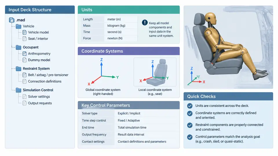
Before any restraint system can be optimized, the analyst must build a MADYMO model that is numerically consistent, physically interpretable, and reproducible. This chapter focuses on the four foundations that determine whether a restraint model behaves correctly: the structure of the input deck, the unit system, the coordinate conventions, and the control parameters that govern solver behavior. Errors in any of these areas typically produce results that look plausible but are physically wrong, so they deserve explicit attention before meshes, airbags, or belt routings are added.
Input deck structure
A MADYMO input deck is a plain-text file organized into named data blocks. Each block begins with a keyword and ends when the next top-level keyword appears. The most common blocks in a restraint analysis are:
GENERAL— global settings such as gravity, time step, and output frequency.UNITS— declares the unit system used throughout the deck.SYSTEM.MODEL— selects the multibody or finite element formulation.BODY/SYSTEM.MB— rigid bodies, joints, and inertia properties.FE_MODEL— finite element meshes for belts, airbags, and contact surfaces.CONTACT— contact definitions between FE and multibody entities.LOAD— prescribed motions, accelerations, or initial velocities.OUTPUT— requested time-history and animation output.
The order of blocks is not arbitrary. UNITS and GENERAL must appear before any block that references physical quantities, because MADYMO resolves unit-dependent values at read time. A typical restraint deck opens with UNITS, then GENERAL, then the system definition, then FE parts, then contacts, and finally loads and outputs. Keeping this order makes the deck readable and prevents silent unit mismatches.
INCLUDE statements to share the occupant, belt, and airbag definitions across cases. This avoids divergence between variants and makes regression testing practical.Units
MADYMO does not enforce a single unit system; it enforces consistency. The UNITS block declares the base units for length, mass, time, and angle, and all derived quantities follow from those choices. Two systems dominate restraint practice:
| Quantity | SI (mm-based) | Legacy (m-based) |
|---|---|---|
| Length | mm | m |
| Mass | kg | kg |
| Time | ms | s |
| Force | kN | N |
| Stress | GPa | Pa |
| Acceleration | mm/ms² | m/s² |
The mm–kg–ms system is convenient for occupant safety because accelerations in mm/ms² are numerically equal to g when divided by 9810, and belt forces in kN match test data directly. The critical rule is that every numeric value in the deck must be expressed in the declared system. A belt stiffness entered in N/mm while the deck declares mm–kg–ms will be interpreted as kN/mm, producing a belt that is a thousand times too stiff. This is one of the most common and most damaging setup errors.
Coordinate systems
MADYMO uses a right-handed Cartesian coordinate system. The vehicle coordinate system is the reference frame for the occupant, belt anchorages, and airbag module. The standard automotive convention is:
- X — positive forward, along the vehicle longitudinal axis.
- Y — positive to the left, from the driver's perspective.
- Z — positive upward, opposite to gravity.
Gravity is therefore defined as -9.81 m/s² in Z, or in the mm–kg–ms system as -9810 mm/ms². Rotations follow the right-hand rule about each axis: roll about X, pitch about Y, yaw about Z. Every body, joint, and FE node is positioned in this frame unless a local coordinate system is explicitly declared.
Local coordinate systems are essential for restraint components. A belt retractor, for example, is best defined in a local frame aligned with the belt pull direction, while the airbag module is defined in a frame aligned with its deployment axis. MADYMO allows a local system to be attached to a body via ORIENTATION and POSITION entries. When a local frame is used, all subsequent geometry for that component is expressed in the local frame, and the transformation to the global frame is handled internally. The analyst must therefore track which frame each value belongs to; mixing global and local coordinates without conversion is a frequent source of misplaced anchorages.
Key control parameters
The GENERAL block and the solver control entries determine how the simulation advances in time and how output is produced. The parameters below are the ones most often adjusted during restraint tuning.
| Parameter | Typical value | Effect |
|---|---|---|
TIME_STEP | 1e-3 ms (FE), 1e-2 ms (MB) | Smaller steps improve stability but increase runtime. |
END_TIME | 120–150 ms | Must cover the full occupant excursion and rebound. |
GRAVITY | -9810 mm/ms² in Z | Sets the static pre-load on the occupant and belt. |
CONTACT_THICKNESS | 1–2 mm | Controls penetration tolerance in FE contact. |
DAMPING | 0.1–0.3 | Stabilizes belt and airbag dynamics. |
OUTPUT_FREQ | 0.5–1 ms | Time-history resolution for injury criteria. |
Two parameters deserve special attention. First, TIME_STEP in an explicit FE formulation is bounded by the Courant condition: the step must be smaller than the time for a stress wave to cross the smallest element. For a belt element of 5 mm with a wave speed of 2000 m/s, the stable step is about 2.5e-3 ms. Exceeding this produces numerical instability that manifests as exploding nodal velocities. Second, END_TIME must be long enough to capture the rebound phase; a common mistake is to stop at 80 ms, which truncates the occupant's forward excursion and under-reports chest deflection.
Practical setup sequence
A reproducible restraint model is built in a fixed order. Start by declaring UNITS and GENERAL, then define the vehicle coordinate system and gravity. Add the occupant multibody with its joints and inertia, then the belt FE mesh with its anchorages in vehicle coordinates. Add the airbag FE mesh with its module frame, then define contacts between belt, airbag, and occupant. Finally, add the load case (sled pulse or prescribed acceleration) and the output requests. Run a short 10 ms check with the airbag disabled to verify belt routing and occupant kinematics before enabling the full restraint system.
When these foundations are correct, the model becomes a reliable platform for the optimization work in later chapters. When they are not, no amount of parameter tuning will produce physically meaningful restraint performance.