1. Introduction to MADYMO for restraint sys
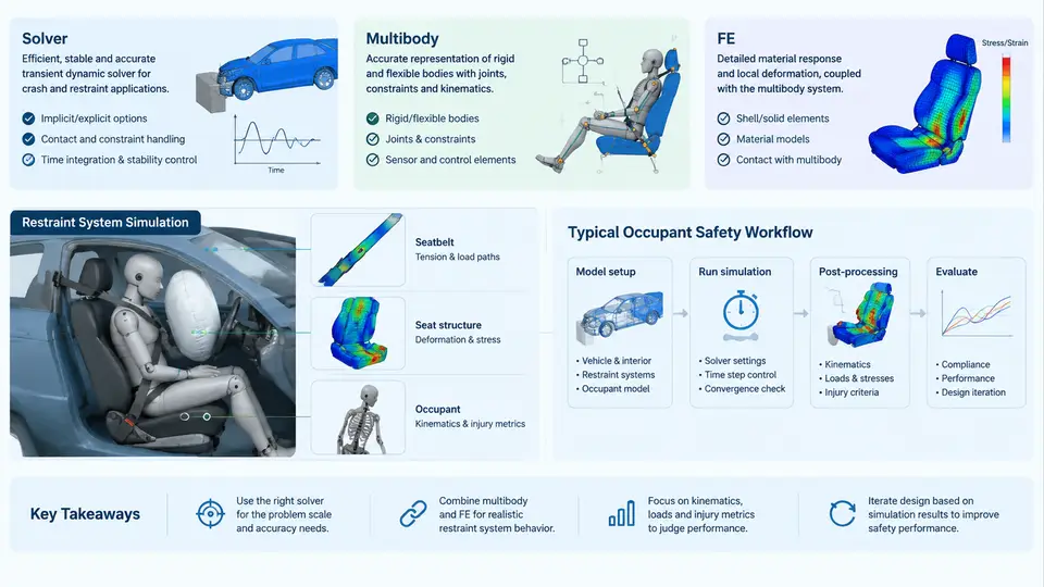
MADYMO (Mathematical Dynamic Model) is a dedicated multi-body and finite element solver developed for the simulation of occupant kinematics and injury biomechanics. In restraint system engineering, it occupies a specific niche: it is not a general-purpose structural FEA package, and it is not a rigid-body dynamics tool for machinery. It is a solver built around the physics that matters in a crash event — large rigid-body motion, joint articulation, contact, belt routing, airbag deployment, and the deformation of compliant structures — and it is used to answer questions such as: how far does the occupant move, when does the head contact the airbag, what forces are transmitted through the belt, and what injury criteria result.
This chapter establishes the vocabulary and the workflow that the remaining chapters build on. It covers what the solver actually computes, how the multi-body and finite element formulations differ and cooperate, and how a typical restraint design study is structured from input deck to injury metric.
The solver at a glance
MADYMO is an explicit, time-integration solver. The equations of motion are advanced with a small, stable time step, and the state of the model at time t+Δt is computed from the state at time t. There is no global stiffness matrix assembly and no Newton iteration for equilibrium, which is why the solver handles the severe nonlinearity of a crash — contact, folding, belt slip, bag inflation — without convergence failures. The trade-off is that the time step is limited by the smallest, stiffest element or the stiffest contact, so a single poorly conditioned component can slow the entire run.
Two formulations coexist in one model:
- Multi-body (MB) — bodies with mass and inertia connected by kinematic joints (spherical, revolute, translational, bracket, etc.). MB is computationally cheap and is the natural choice for the occupant skeleton, the steering column, and any component whose deformation is not of interest.
- Finite element (FE) — shell, solid, membrane, and belt elements with a material model. FE is used where deformation and stress matter: the airbag fabric, the instrument panel, the seat frame, the knee bolster, and increasingly the occupant's chest and pelvis when rib or pelvic fracture risk is being assessed.
The two formulations are coupled through supports and contacts. An FE airbag can be attached to an MB steering column; an MB occupant can contact an FE instrument panel. This hybrid capability is the defining feature of MADYMO for restraint work: it lets the engineer spend computation only where the physics demands it.
Multi-body and FE capabilities in restraint work
In a frontal driver-side study, a typical model contains an MB occupant (head, neck, thorax, pelvis, upper and lower extremities), an MB or FE steering column, an FE airbag, an FE or MB seat, and a belt modelled with FE membrane or belt elements routed through a retractor, slip ring, and buckle. The belt is a good illustration of why the hybrid approach matters: it must slide through the D-ring, lock at the retractor, and stretch under load. Modelling it as MB would lose the load distribution across the chest; modelling the entire occupant as FE would multiply the run time without improving the answer.
Contact is handled by a penalty formulation. Penetration between a contact pair generates a restoring force proportional to the penetration depth and a contact stiffness. The contact stiffness is a critical numerical parameter: too low and bodies interpenetrate visibly; too high and the time step collapses. MADYMO exposes this through contact characteristics, and the practical rule is to start from the default, inspect the penetration in the animation, and adjust only when penetration exceeds a small fraction of the element size.
A typical occupant safety workflow
The workflow below is the backbone of every subsequent chapter. It is presented as a sequence because the dependencies are real — you cannot validate a belt routing before the occupant is positioned, and you cannot trust an injury value before the model is correlated.
Each stage produces a specific artefact. Stage 1 produces the input deck (XML for MADYMO). Stage 2 produces a positioned model with a defined belt path. Stage 3 produces the load case definition — the acceleration pulse applied to the sled, the airbag trigger time, and the belt system parameters. Stage 4 produces the simulation output. Stage 5 produces the time histories and animation. Stage 6 produces a correlated model. Stage 7 produces the injury numbers that feed the design decision.
What the solver actually outputs
MADYMO writes time-history data for every requested quantity and a binary animation file. For restraint work the quantities that matter are:
| Output | Typical use | Representative target (frontal, 50th percentile male) |
|---|---|---|
| Head resultant acceleration | HIC15 calculation | HIC15 < 700 |
| Chest deflection | Rib fracture risk | < 50 mm (or < 63 mm depending on criterion) |
| Belt force at retractor | Load limiter sizing | 3.5–4.5 kN typical plateau |
| Bag internal pressure | Vent sizing, bottom-out check | Peak ~200–300 kPa, then decay |
| Femur axial force | Knee bolster / lower extremity | < 10 kN per leg |
The values above are representative engineering targets, not results from a specific run. They are included to show the order of magnitude the engineer is working with and to make the point that the solver output is only useful when it is compared against a criterion.
Why correlation comes before optimisation
A common failure mode in restraint simulation is to skip correlation and go straight to design iteration. The model then produces plausible-looking numbers that are systematically offset from reality — the head may contact the bag 15 ms early because the belt stiffness is too high, or the chest deflection may be under-predicted because the seat back is too rigid. Optimising against an uncorrelated model produces a design that is optimal for the model and wrong for the vehicle.
Correlation is therefore not a formality. It means matching the model against sled or vehicle test data on the quantities that drive the injury metrics: head acceleration timing and peak, belt force profile, and occupant forward excursion. The tuning knobs are contact stiffness, friction coefficients, belt material properties, and airbag mass flow. When the model matches the test within a defined tolerance — typically 10–15% on peak values and a few milliseconds on timing — it is fit to support design decisions.
What this course covers
The chapters that follow move through the workflow in the order an engineer actually works: occupant and restraint modelling, belt and airbag definition, load case setup, contact and material calibration, correlation against test data, injury metric extraction, and finally design optimisation. Each chapter assumes the vocabulary introduced here — MB versus FE, contact stiffness, time step, load limiter, trigger time — and each builds a model that can be run and inspected.
The goal is not to memorise the solver's keyword reference. It is to develop the judgement to know which formulation to use, which parameters to tune, and when a result is trustworthy enough to make a restraint design decision on.