3. Building a baseline frontal impact model
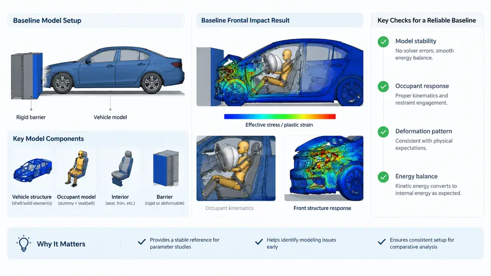
A baseline frontal impact model is the reference configuration against which every subsequent restraint design, parameter study, and optimization run is compared. If the baseline is inconsistent — a belt routed through the wrong slip ring, a seat cushion angle that does not match the CAD surface, or an occupant positioned with an incorrect H-point — then every delta you measure later is contaminated. This chapter walks through the four pillars of a defensible baseline: the vehicle environment, the seat structure, the belt routing, and the occupant positioning. The goal is a model that is geometrically faithful, numerically stable, and reproducible by another engineer using only your documented inputs.
3.1 Vehicle Environment: Defining the Reference Frame
MADYMO models are built in a right-handed Cartesian coordinate system. For frontal impact, the conventional vehicle frame places the X-axis pointing forward (direction of travel), the Y-axis pointing to the left, and the Z-axis pointing upward. Gravity acts in the negative Z direction. Every rigid body, joint, and initial velocity you define must be consistent with this frame. A common mistake is importing CAD geometry in a Y-up convention and then applying a forward acceleration in the wrong axis, which produces a lateral occupant excursion that looks like a side impact.
The vehicle environment in a frontal sled or full-vehicle model consists of three essential elements:
- Floor and toe pan: A rigid or deformable surface that constrains the occupant's feet and lower legs. In a sled model, this is typically a fixed plane; in a full-vehicle model, it may be a deformable FE mesh.
- Instrument panel and knee bolster: Contact surfaces that the occupant's knees and tibia may strike. These are usually defined as rigid planes or ellipsoids with a specified friction coefficient (typically 0.3–0.5 for leather/plastic contact).
- Firewall and A-pillar: Reference geometry for belt anchor points and for defining the occupant compartment's intrusion boundary.
For a baseline model, it is acceptable to represent the vehicle environment as rigid bodies. The key is to document the position and orientation of each surface relative to the vehicle origin. A practical approach is to create a single SYSTEM named VEHICLE_ENV that contains all static environment bodies, so that the occupant and restraint systems can be moved independently without disturbing the environment.
3.2 Seat Model: Geometry, Stiffness, and Adjustment
The seat is not a passive backdrop — it governs occupant kinematics through cushion compression, backrest deflection, and friction. In MADYMO, a seat is typically represented by a combination of rigid planes (for the cushion and backrest) and a spring-damper system that captures the foam stiffness. The baseline seat model should include:
- Cushion plane: Defined by a point and a normal vector. The cushion angle (typically 5–15 degrees from horizontal) affects pelvis rotation and submarining risk.
- Backrest plane: Defined similarly, with a recline angle (typically 20–30 degrees from vertical). The backrest angle directly influences the occupant's initial torso orientation.
- Seat stiffness: A force-deflection curve applied to the cushion and backrest contacts. For a baseline model, a linear stiffness of 20–50 N/mm is a reasonable starting point for a standard automotive seat.
- Friction: A coefficient of friction between the occupant and the seat surfaces, typically 0.3–0.5.
The seat adjustment parameters — fore-aft position, cushion height, and backrest angle — must be set to the nominal design position. In MADYMO, this is often done by defining the seat geometry in a local coordinate system and then applying a POSITION or ORIENTATION to the seat system. Document the nominal values in a table, as shown below.
| Parameter | Symbol | Nominal Value | Unit |
|---|---|---|---|
| Cushion angle | θc | 10 | deg |
| Backrest angle | θb | 25 | deg |
| Cushion stiffness | kc | 35 | N/mm |
| Backrest stiffness | kb | 25 | N/mm |
| Seat friction | μs | 0.4 | — |
3.3 Belt Routing: Anchors, Slip Rings, and Retractor
The seat belt is the primary restraint in a frontal impact, and its routing determines how forces are distributed across the occupant's body. A baseline belt model consists of four anchor points and one retractor:
- D-ring (shoulder anchor): Located on the B-pillar or seat back, typically at a height of 1.0–1.2 m above the ground and 0.2–0.3 m outboard of the seat centerline.
- Lap anchor outboard: Located at the outboard side of the seat, near the floor.
- Lap anchor inboard: Located at the inboard side of the seat, often with a buckle pretensioner.
- Retractor: Located at the D-ring or on the B-pillar, with a defined payout characteristic.
In MADYMO, the belt is modeled as a series of BELT segments connected by SLIP RING elements. The slip ring allows the belt to slide freely, which is essential for realistic force distribution. The retractor is modeled as a RETRACTOR element with a force-limiting characteristic. For a baseline model, a constant force limit of 4 kN is a common starting point for a driver-side belt.
The belt routing must be checked for two common errors: (1) the belt passing through the occupant's body, which causes non-physical contact forces, and (2) the belt not engaging the slip ring, which results in a rigid connection and unrealistic load paths. A visual check in the MADYMO viewer, combined with a plot of belt force versus time, will reveal both issues.
3.4 Occupant Positioning: H-Point, Posture, and Initial Conditions
The occupant model — typically a Hybrid III 50th percentile male in MADYMO — must be positioned so that its H-point coincides with the seat reference point (S-point) defined by the seat geometry. The H-point is the pivot point of the pelvis and thigh, and it determines the occupant's overall posture. In MADYMO, the occupant is positioned by specifying the coordinates of the H-point and the initial joint angles of the pelvis, torso, and limbs.
For a baseline frontal impact model, the following initial conditions are recommended:
- H-point: Aligned with the seat cushion plane, typically 0.25–0.30 m above the cushion surface.
- Pelvis angle: 20–25 degrees from vertical, matching the seat cushion angle.
- Torso angle: 20–25 degrees from vertical, matching the backrest angle.
- Knee angle: 90–110 degrees, with the feet resting on the toe pan.
- Initial velocity: The entire occupant-vehicle system is given an initial velocity equal to the impact speed (e.g., 50 km/h = 13.89 m/s) in the negative X direction, or the vehicle is decelerated by a prescribed pulse while the occupant remains at initial velocity.
The choice between these two approaches — initial velocity versus prescribed pulse — depends on whether you are modeling a full vehicle or a sled. For a sled model, the pulse is applied to the sled frame, and the occupant is initially at rest relative to the sled. For a full-vehicle model, the vehicle is given an initial velocity and decelerated by a barrier contact or a prescribed pulse.
3.5 Verification Checklist for the Baseline Model
Before running a full simulation, verify the following items. This checklist is designed to be used as a pre-run gate; if any item fails, correct it before proceeding.
| # | Check Item | Expected Result | Common Failure Symptom |
|---|---|---|---|
| 1 | Coordinate frame consistency | X forward, Z up, gravity in −Z | Occupant moves laterally or upward |
| 2 | H-point alignment | H-point coincides with seat S-point | Occupant sinks into or floats above seat |
| 3 | Belt routing | Belt passes through slip rings, no body penetration | Belt force spikes or drops to zero |
| 4 | Retractor force limit | 4 kN constant (baseline) | Belt force exceeds 6 kN without limit |
| 5 | Initial velocity | 13.89 m/s in −X (50 km/h) | Occupant remains stationary relative to ground |
| 6 | Contact definitions | Feet on toe pan, knees near bolster | Feet pass through floor or knees miss bolster |
Once these checks pass, run a short simulation (20–30 ms) with the prescribed pulse and plot the occupant's head and chest acceleration. A well-built baseline will show a smooth acceleration rise, a peak within the expected range (typically 40–60 g for head, 30–50 g for chest at 50 km/h), and no numerical spikes. If you see spikes, check the contact stiffness and the belt slip ring definitions — these are the most common sources of numerical instability in frontal impact models.