1. MADYMO in occupant safety engineering
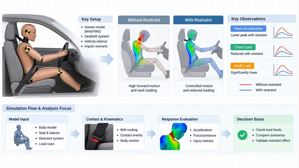
MADYMO (Mathematical Dynamic Model) is a finite-element and multibody simulation package developed by TASS International (now part of Siemens) and used throughout the automotive industry for occupant safety analysis. Its core purpose is to predict how the human body interacts with vehicle interiors and restraint systems during a crash event, so that engineers can evaluate injury risk before physical prototypes exist. This chapter establishes the conceptual and architectural foundation for the rest of the course: what problems MADYMO is designed to solve, how its solvers are organized, and where it fits in the restraint system development cycle.
1.1 Scope of Occupant Safety Simulation
Occupant safety engineering addresses a simple question with enormous complexity: when a vehicle decelerates violently, what happens to the people inside? The physical event involves contact, large deformation, friction, and the nonlinear behavior of both biological tissue and engineered structures. MADYMO approaches this problem by separating the occupant from the environment and modeling each with the numerical method best suited to its behavior.
The scope of MADYMO covers frontal, side, rear, and rollover impact scenarios; airbag deployment and out-of-position (OOP) loading; seatbelt routing and pretensioner/load-limiter behavior; child restraint systems (CRS); pedestrian protection; and occupant classification studies. It is also used for regulatory and consumer-test correlation, such as Euro NCAP and FMVSS 208 evaluations, and increasingly for virtual testing that reduces the number of physical sled and vehicle tests.
A key distinction from a pure crashworthiness code is that MADYMO is occupant-centric. The vehicle structure may be represented by a simplified deceleration pulse rather than a full body-in-white model, which keeps runtimes practical while preserving the loading conditions that matter for injury prediction.
1.2 Solver Architecture: Multibody and Finite Element Coupling
MADYMO's architecture is built on two complementary solvers that can be used independently or coupled in a single model:
- Multibody (MB) solver: Rigid bodies connected by kinematic joints (revolute, translational, spherical, universal, etc.) and force interactions. This is efficient for representing the occupant skeleton, seat structure, and belt routing. The MB solver uses a recursive formulation that scales well with many bodies.
- Finite Element (FE) solver: Deformable bodies discretized into shell, solid, membrane, and beam elements. This is used for airbags, seat cushions, foam, and the vehicle interior surfaces where contact and material nonlinearity dominate.
The two solvers exchange information at coupling interfaces. An FE airbag can push against an MB occupant, and the MB occupant's contact forces feed back into the FE mesh. This coupling is what allows a single MADYMO model to capture both the gross kinematics of the body and the local deformation of the restraint hardware.
Time integration is explicit for the FE solver, with a critical time step governed by the smallest element size and material wave speed. The MB solver uses its own integration scheme, and the coupling is synchronized at each communication interval. Understanding this architecture matters because it determines model stability, runtime, and which phenomena can be represented faithfully.
1.3 The Role of MADYMO in Restraint System Development
Restraint system development follows a V-model: requirements and targets are defined at the top, subsystem designs are developed in the middle, and verification and validation close the loop. MADYMO occupies the left side of the V, where design alternatives are explored virtually, and supports the right side through correlation with test data.
In practice, the workflow typically proceeds as follows. First, a baseline model is built from CAD geometry, material data, and a validated occupant model such as the Hybrid III 50th percentile male or the THOR dummy. Second, a load case is defined using a vehicle deceleration pulse measured from a sled or full-vehicle test. Third, restraint parameters—belt anchor positions, pretensioner timing, load-limiter force, airbag vent size, and inflator mass flow—are varied to meet injury criteria. Fourth, results are post-processed into metrics such as HIC, chest deflection, Nij, and femur force, and compared against targets.
The value of MADYMO here is iteration speed. A single sled test may cost tens of thousands of dollars and weeks of lead time; a MADYMO run can be completed in hours and repeated with modified parameters. This does not eliminate physical testing, but it shifts the engineer's effort from trial-and-error hardware builds to informed design selection.
1.4 A Concrete Example: Frontal Driver Airbag Study
Consider a frontal 56 km/h rigid barrier load case for a driver-side restraint system. The input pulse is a deceleration-time history applied to the vehicle body. The occupant model is a Hybrid III 50th percentile male positioned per the seating procedure. The restraint system includes a three-point belt with a 4 kN load limiter and a 60 L driver airbag with a single vent.
A parameter study might vary the airbag vent diameter from 25 mm to 45 mm and the load-limiter force from 3 kN to 5 kN. The observable outputs are head acceleration, chest deflection, and belt force. A typical finding is that a larger vent reduces internal pressure and membrane tension, lowering head acceleration but increasing chest deflection because the occupant moves further forward. The engineer must find the combination that satisfies both HIC and chest deflection targets simultaneously.
This example illustrates the central trade-off in restraint design: energy must be absorbed, but not so abruptly that peak forces injure the occupant, and not so slowly that the occupant strikes the interior. MADYMO makes this trade-off visible and quantifiable before hardware exists.
1.5 Model Setup and Verification Practices
Before trusting any result, the model must be verified and validated. Verification checks that the numerical implementation is correct—for example, that a belt element produces the expected force under a prescribed displacement. Validation compares simulation output against physical test data, such as sled acceleration, belt force, and dummy kinematics.
Common failure symptoms and their causes include:
- Negative volume in an FE airbag: time step too large or contact definition too stiff; reduce time step or adjust contact stiffness.
- Occupant penetrating the seat: missing or incorrect contact definition between the occupant and seat surfaces.
- Unrealistic belt forces: incorrect belt routing, slipring friction, or retractor characteristics.
- Energy imbalance: hourglassing in under-integrated elements or unstable coupling; check element formulation and coupling stiffness.
These checks are not optional. A model that runs to completion but violates physics will produce misleading injury metrics and poor design decisions.
1.6 Why This Architecture Matters for the Rest of the Course
Every later chapter builds on the distinction introduced here. When you define an airbag, you are working in the FE domain. When you position a dummy and define its joints, you are working in the MB domain. When you route a seatbelt, you are often working in both. Recognizing which solver owns a given behavior tells you where to look when a model misbehaves and which parameters are physically meaningful to adjust.
Similarly, the development loop shown above is the context for every modeling decision. A parameter is not adjusted because it is convenient; it is adjusted because it maps to a real design variable and because its effect on injury metrics can be observed and judged. Keeping that mapping explicit is what separates a useful simulation from a numerical exercise.
With the scope, architecture, and development role established, the next step is to become fluent in the model-building environment itself—how bodies, joints, contacts, and loads are declared and organized in a MADYMO input deck.