3. Input data requirements for calibration
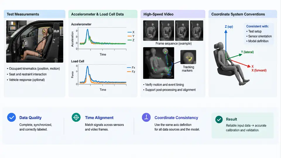
Calibration quality is bounded by input data quality. A MADYMO occupant model can only be tuned to reproduce behavior that is actually observable in the reference data. Before touching any model parameter, the engineer must assemble a complete, internally consistent measurement package: physical test measurements, accelerometer and load cell channels, high-speed video, and a documented coordinate system convention. This section defines what each data type contributes, how to verify it, and how to prepare it for use in MADYMO.
3.1 Test Measurements: The Physical Reference
Calibration targets come from physical tests — sled tests, drop towers, pendulum impacts, or full-scale crash tests. Each test provides a set of scalar and time-history measurements that define the "truth" the model must match. Typical channels include:
- Sled/vehicle kinematics: longitudinal, lateral, and vertical acceleration of the buck or vehicle body at defined reference points.
- Occupant kinematics: head CG acceleration (triaxial), chest acceleration, pelvis acceleration, and sometimes angular rate from gyros.
- Restraint loads: seat belt webbing force (load cell in the belt), buckle force, retractor force, and airbag pressure or force.
- Displacement: seat track position, steering column stroke, knee bolster intrusion, and belt payout.
Each channel must be traceable to a sensor location, a mounting orientation, and a calibration certificate. A common failure mode is a channel with correct magnitude but inverted sign, which produces a model that appears to "almost" match until the engineer discovers the polarity error. Always record the sensor's positive axis direction relative to the vehicle coordinate system.
3.2 Accelerometer and Load Cell Data
Accelerometers and load cells are the primary quantitative inputs. Their data must be conditioned before use:
- Filtering: Apply the filter class specified by the test standard (e.g., SAE J211 CFC 60 for occupant accelerations, CFC 180 for belt forces). MADYMO output should be filtered with the same class for comparison.
- Zero offset: Remove pre-trigger bias by subtracting the mean of a quiet window (typically 50–100 ms before T0).
- Time alignment: Align all channels to a common T0 using a trigger signal or a known event (e.g., sled pulse onset). Misalignment of even 2–3 ms can shift peak timing and mislead calibration.
- Units: Convert to consistent SI or standard engineering units (m/s², g, N, kN) and document the conversion.
Load cells in belts require special attention: the measured force includes belt routing friction and pretensioner effects. For calibration, the belt force at the load cell location is the target, not the force at the occupant contact point. The model's belt element output must be extracted at the equivalent location.
3.3 High-Speed Video
High-speed video provides the spatial context that transducers cannot. It is used to:
- Verify occupant posture and initial position before impact.
- Track body segment motion (head, torso, pelvis) frame by frame.
- Identify contact timing between occupant and airbag, belt, or interior surfaces.
- Detect anomalies such as belt slip, airbag misfire, or out-of-position seating.
For calibration, video is digitized to extract displacement histories at marked targets. Typical setup: 1000 fps, calibrated grid in the field of view, and at least one camera perpendicular to the primary motion plane. The digitized displacement is then compared against MADYMO's predicted marker positions. Video-derived data is lower frequency than accelerometer data but is essential for validating the overall kinematic path, not just peak values.
3.4 Coordinate System Conventions
MADYMO uses a right-handed Cartesian coordinate system. The standard vehicle coordinate system is:
- X: forward (positive toward vehicle front)
- Y: left (positive toward driver's left)
- Z: up (positive upward)
All input data — accelerometer axes, load cell directions, video digitization, and model geometry — must be expressed in this system or transformed into it. The transformation must be documented: origin location, axis rotations, and any sign flips. A frequent error is mixing SAE J211 sign conventions (where accelerometer positive is often defined differently) with MADYMO's system without correction.
For occupant models, the local body coordinate systems (head, chest, pelvis) also follow right-handed conventions, but their origins are defined by the model's anatomical reference points. When comparing model output to test data, ensure the model's output marker is at the same physical location as the test sensor.
3.5 Practical Data Preparation Workflow
The following workflow is a reproducible sequence for preparing a calibration dataset. It assumes a sled test with a Hybrid III 50th percentile occupant and a three-point belt.
- Collect raw channels: Export all accelerometer and load cell time histories from the data acquisition system. Record sample rate (typically 10 kHz), channel names, and sensor serial numbers.
- Apply filtering: Use the filter class required by the test protocol. For occupant accelerations, CFC 60 is standard; for belt forces, CFC 180. Document the filter type (Butterworth, 4th order, zero-phase).
- Zero and align: Subtract the mean of the 50 ms pre-trigger window from each channel. Align all channels to the sled pulse onset (T0) using the trigger channel.
- Transform coordinates: If the test data is in SAE J211 sign convention, convert to MADYMO's right-handed system. For example, a chest accelerometer measuring positive forward in SAE may need a sign flip if its axis is defined opposite to MADYMO's X.
- Digitize video: Extract marker positions at 1 ms intervals. Convert pixel coordinates to millimeters using the calibration grid. Transform to MADYMO CS.
- Build the comparison dataset: Create a table with columns: time, test channel value, MADYMO channel value, difference. This table drives the calibration loop.
3.6 Verification Checklist
Before starting calibration, verify the following for each channel:
| Check | Acceptance Criterion | Action if Failed |
|---|---|---|
| Sensor location documented | Coordinates in vehicle CS | Re-measure or consult test report |
| Polarity correct | Positive direction matches MADYMO CS | Flip sign in preprocessing |
| Filter class applied | Matches test standard | Re-filter raw data |
| Zero offset removed | Pre-trigger mean ≈ 0 | Subtract bias |
| Time alignment | All channels share T0 | Cross-correlate with trigger |
| Units consistent | SI or documented engineering units | Convert and document |
| Video calibration | Grid scale verified | Re-digitize with correct scale |
Once this checklist is complete, the dataset is ready for the calibration loop. The next section will use this dataset to tune MADYMO model parameters, but the quality of that tuning is directly limited by the rigor applied here.