1. MADYMO in occupant safety engineering
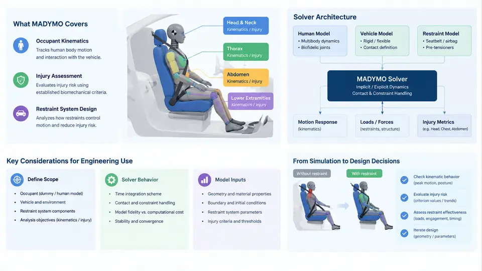
MADYMO (Mathematical Dynamic Model) is a multi-body and finite-element solver dedicated to occupant safety engineering. It is used to predict how a human body moves and loads inside a vehicle during a crash, and to evaluate whether the restraint system — seat belts, airbags, seat structure, and pretensioners — keeps injury measures below regulatory and consumer-test thresholds. This chapter establishes the scope of the tool, explains how its solvers are organized, and shows where MADYMO sits in the restraint design workflow.
Scope: What MADYMO Is Used For
MADYMO addresses three broad problem classes:
- Occupant kinematics and injury prediction — simulating the head, neck, thorax, pelvis, and lower extremities during frontal, side, rear, and rollover impacts, and computing injury criteria such as HIC, Nij, chest deflection, and pelvis acceleration.
- Restraint system design and optimization — evaluating airbag venting, tether routing, belt geometry, pretensioner force, load limiter characteristics, and seat cushion stiffness before hardware is built.
- Regulatory and consumer-rating support — reproducing FMVSS 208, ECE R94/R95, Euro NCAP, and C-NCAP load cases to check compliance and rating margins.
The tool is not a full-vehicle crash solver. It focuses on the occupant and the immediate restraint environment. The vehicle deceleration pulse, structural intrusion, and airbag deployment timing are typically supplied as boundary conditions from a full-vehicle FE model or from test measurements.
Solver Architecture
MADYMO combines two solver technologies in one simulation:
- Multi-body (MB) dynamics — rigid bodies connected by kinematic joints and force elements. This is efficient for representing the occupant skeleton, the belt system, and the seat as a system of linked rigid segments. Contact is handled through force-penetration functions.
- Finite element (FE) — deformable bodies for airbags, seat cushions, belt webbing, and detailed human body models. FE captures large deformation, membrane behavior, and gas flow inside airbags.
The two domains are coupled: an FE airbag can interact with an MB occupant, and an FE belt can wrap around an MB pelvis. This coupling is what makes MADYMO practical — the analyst uses MB where speed matters and FE where deformation detail matters.
Time integration is explicit. The solver advances the solution with a small stable time step determined by the stiffest element or contact stiffness in the model. A typical occupant model runs at 0.5–2 μs per step for FE-dominated cases, or larger steps for pure MB models. The simulation duration for a frontal impact is usually 120–150 ms, which is enough to capture the primary occupant loading and the early rebound phase.
Role in Restraint System Design
In a typical restraint development program, MADYMO occupies the middle of the V-model. Upstream, full-vehicle FE simulations or sled tests provide the deceleration pulse and interior geometry. Downstream, the validated occupant model supports design decisions and hardware tests.
The workflow usually follows this sequence:
- Build the occupant model — select a dummy (Hybrid III 50th, THOR, or a human body model) and position it according to the seating reference point and the target posture.
- Define the environment — import the seat, floor, toe pan, and instrument panel geometry; apply the deceleration pulse to the vehicle reference frame.
- Model the restraint system — belt routing with slip rings and retractor, airbag with folded geometry and gas inflow, pretensioner and load limiter characteristics.
- Run the simulation — check the animation for unrealistic penetrations, belt slip, or airbag misfolding.
- Evaluate injury criteria — extract HIC, Nij, chest deflection, and femur loads; compare against targets.
- Iterate on design parameters — adjust vent size, tether length, belt anchor position, or load limiter force until targets are met.
A concrete example clarifies the parameter sensitivity. Suppose a frontal 56 km/h sled pulse is applied, and the baseline model gives HIC = 780 and chest deflection = 42 mm. The target is HIC ≤ 700 and chest deflection ≤ 35 mm. The analyst reduces the load limiter force from 4.0 kN to 3.2 kN and increases the airbag vent diameter from 30 mm to 40 mm. The expected effect is earlier belt payout and softer airbag pressure, which reduces chest loading but may increase head forward excursion. After re-running, the analyst checks whether head contact with the airbag still occurs before rebound and whether the neck tension stays within limits. This trade-off — chest load versus head excursion — is the central design tension in frontal restraint systems, and MADYMO is the tool that quantifies it.
Why MADYMO Remains Relevant
Modern occupant safety faces new challenges: diverse occupant sizes, out-of-position occupants, reclined seating, and battery-electric vehicle interiors with new seat geometries. MADYMO's MB–FE coupling allows rapid exploration of these scenarios. A pure FE approach would be more detailed but far slower for the dozens or hundreds of design iterations required. A pure MB approach would be faster but unable to capture airbag folding and fabric behavior. MADYMO's architecture is a deliberate compromise that matches the engineering need: enough fidelity to predict injury trends, enough speed to support design iteration.
Practical Considerations for New Users
Three points are worth emphasizing before moving to model construction. First, MADYMO results are only as good as the boundary conditions. A wrong deceleration pulse or an incorrect seat geometry will produce misleading injury numbers regardless of solver accuracy. Second, the MB–FE coupling requires attention to contact definitions: penetration depth, friction coefficient, and contact stiffness all influence the force transfer between the occupant and the restraint. Third, validation against sled or vehicle tests is not optional. A model that has not been correlated with at least one physical test should be treated as a trend predictor, not a compliance tool.
With the scope, architecture, and workflow established, the next step is to examine how the multi-body and finite-element formulations are actually constructed — the subject of the following chapters.