1. Introduction to MADYMO for human body mo
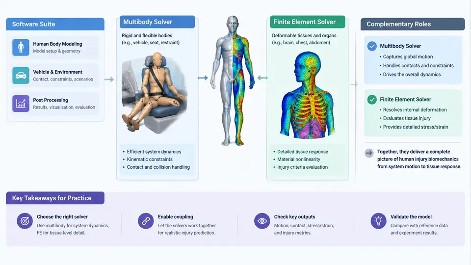
MADYMO (Mathematical Dynamic Model) is a commercial multi-physics simulation suite developed by TASS International (now part of Siemens Digital Industries Software) for crash safety, occupant protection, and injury biomechanics. Its defining characteristic is a hybrid solver architecture: rigid-body multibody dynamics and nonlinear finite element analysis coexist in a single model, coupled through shared interfaces. This hybrid capability is what makes MADYMO particularly well suited to human body modeling, where a deformable thorax, a rigid pelvis, and a kinematic restraint system must all interact within one simulation.
1.1 Why a Hybrid Solver Matters for Injury Biomechanics
Injury biomechanics asks two questions simultaneously: how does the body move? and how much does tissue deform? Multibody (MB) solvers answer the first question efficiently. They represent bodies as rigid segments connected by kinematic joints (spherical, revolute, translational, bracket, etc.), each with defined stiffness and damping. Degrees of freedom are small — typically tens to hundreds — so a full-body occupant kinematics simulation runs in seconds to minutes. However, MB models cannot predict local tissue strain, rib fracture, or brain deformation, because rigid bodies do not deform.
Finite element (FE) solvers answer the second question. They discretize deformable structures into elements and compute stress, strain, and failure. A detailed FE thorax model may contain 50,000–500,000 elements and requires explicit time integration with small stable time steps. Running a full FE vehicle interior plus a full FE human body is computationally expensive and often impractical for design iteration.
MADYMO resolves this tension by letting both solver types operate in the same simulation. A typical occupant model uses MB segments for the pelvis, spine, and limbs, and an FE mesh for the thorax, abdomen, or brain. The coupling interface transfers forces and displacements between the two domains at each time step. This is the core reason MADYMO became a standard tool in biomechanics research and regulatory restraint development.
1.2 The Software Suite at a Glance
The MADYMO environment is organized around several components that a modeler uses in sequence:
- MADYMO Solver — the core explicit/implicit engine that reads the input deck (
.xmlor legacy.dat) and produces time-history output (.kn3,.ps3,.lsda). - MADYMO Modeler / XMADgic — pre-processing tools for building multibody systems, defining joints, ellipsoids, and FE meshes, and assembling restraint systems.
- MADYMO Viewer — post-processing for animation, contour plots, and signal extraction.
- MADYMO Coupling / Madymo2Simulink — interfaces for co-simulation with MATLAB/Simulink or other CAE environments.
- Human body model libraries — validated occupant models such as the TNO Hybrid III, THOR, and the MADYMO Human Body Model (HBM) family, including the Total Human Model for Safety (THUMS) variants distributed for MADYMO.
For human body modeling specifically, the most important library assets are the ellipsoid-based MB occupant models (fast, used for restraint optimization) and the FE human body models (detailed, used for injury prediction). Many projects start with an MB model to establish kinematics, then switch to an FE model for the critical body region.
1.3 Multibody and FE Solvers: Roles and Coupling
Understanding the division of labor between the two solvers is essential before building any model. The table below summarizes their roles in a typical frontal impact study.
| Aspect | Multibody (MB) solver | Finite element (FE) solver |
|---|---|---|
| Body representation | Rigid segments + joints | Deformable mesh (shells, solids) |
| Typical DOF | 10–500 | 10⁴–10⁶ |
| Output | Acceleration, joint force, contact force | Stress, strain, element failure |
| Injury metrics | HIC, NIC, chest deflection (via spring) | Rib strain, brain von Mises stress, AIS prediction |
| Runtime (frontal, 150 ms) | Seconds to minutes | Hours to days |
| Best use | Kinematics, restraint layout, parameter sweeps | Local tissue injury, fracture risk |
Coupling between the two domains occurs through contact interfaces and kinematic constraints. In MADYMO, an FE thorax can be attached to an MB spine via a BRACKET joint or a set of tied nodes, while the FE mesh contacts the MB airbag and belt through the penalty-based contact algorithm. At each time step, the MB solver computes the motion of the rigid segments; the FE solver computes deformation of the mesh; the coupling algorithm exchanges forces and displacements. The stability of this exchange depends on the time step, contact stiffness, and mass scaling — a common source of simulation failure.
1.4 A Minimal Working Example: Frontal Impact Setup
To make the workflow concrete, consider a simplified frontal impact simulation using an MB occupant model. The goal is to obtain head acceleration and chest deflection for a 50 km/h sled pulse. The steps below reflect a realistic MADYMO input structure; parameter values are illustrative and should be replaced with validated data for actual studies.
<!-- MADYMO input deck (simplified, illustrative) -->
<SYSTEM>
  <MODEL>
    <MULTIBODY>
      <BODY id="pelvis" mass="12.0" inertia="0.15 0.12 0.10"/>
      <BODY id="thorax" mass="25.0" inertia="0.35 0.28 0.22"/>
      <BODY id="head"   mass="4.5"  inertia="0.02 0.02 0.02"/>
      <JOINT id="spine_lower" type="SPHERICAL" body1="pelvis" body2="thorax"/>
      <JOINT id="neck"        type="REVOLUTE"  body1="thorax" body2="head"/>
    </MULTIBODY>
    <FE_MODEL>
      <INCLUDE file="thorax_fe.xml"/>   <!-- deformable thorax mesh -->
    </FE_MODEL>
    <CONTACT>
      <CONTACT_MB_FE body_mb="thorax" fe_part="thorax_fe" stiffness="1.0e6"/>
    </CONTACT>
    <RESTRAINT>
      <BELT type="3-point" anchor="vehicle"/>
      <AIRBAG type="driver" pressure="0.15 MPa"/>
    </RESTRAINT>
  </MODEL>
  <CONTROL>
    <TIME t_end="0.150" dt="1.0e-6"/>
    <OUTPUT type="kn3" interval="0.001"/>
  </CONTROL>
</SYSTEM>
After running the solver, the modeler inspects the .kn3 file in MADYMO Viewer. Key signals to extract are the head resultant acceleration (for HIC₁₅ calculation) and the thorax FE node displacement (for chest deflection). A typical validation check compares the simulated chest deflection against the Hybrid III certification corridor: for a 50 km/h sled pulse, peak deflection should fall within approximately 50–70 mm depending on belt geometry. If the FE thorax shows excessive element distortion or negative volume, the contact stiffness or time step must be adjusted.
1.5 Common Pitfalls in Early MADYMO Human Body Modeling
- Ignoring mass scaling in FE regions. Explicit FE requires a stable time step proportional to the smallest element size. Mass scaling can increase the step but alters inertia; document any scaling factor and verify it does not change the injury outcome.
- Mismatched units. MADYMO uses SI by default (kg, m, s, N). Mixing mm and m in FE mesh coordinates is a frequent source of contact failure.
- Over-constraining the coupling. Tying too many FE nodes to a single MB body creates artificial stiffness. Use distributed coupling or a bracket joint with realistic compliance.
- Neglecting model validation. A model that runs without error is not necessarily correct. Always compare against cadaveric or PMHS test data for the specific loading condition.
With this foundation — the hybrid solver concept, the suite components, and a minimal working example — you are ready to examine the specific human body model families and their validation status in the next chapter.