3. Restraint system components in MADYMO
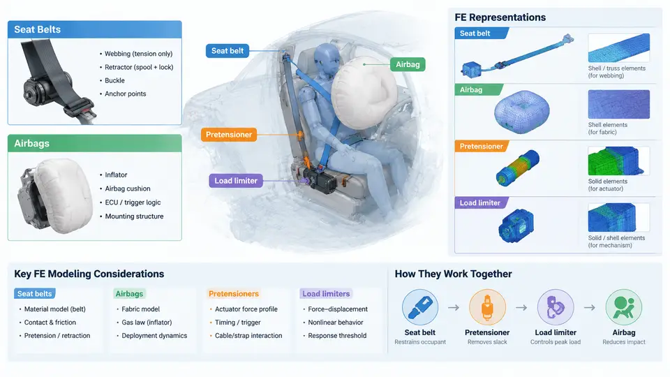
In a MADYMO occupant safety model, the restraint system is what converts a decelerating vehicle into a survivable environment for the occupant. The vehicle body defines the crash pulse; the restraint system defines how that pulse is transferred to the human body. MADYMO provides dedicated, physically parameterized element types for each restraint component, so the modeling task is not to "draw" a belt or an airbag geometrically, but to select the correct element type and populate it with the parameters that govern its mechanical behavior. This section reviews the five core components — seat belts, pretensioners, load limiters, airbags, and the FE representations that carry them — and shows how they interact in a single restraint model.
Seat Belts: Multibody Belt vs. FE Belt
MADYMO offers two fundamentally different belt representations, and choosing between them is the first modeling decision.
The multibody belt (MB belt) is a discrete, lumped-parameter model. The belt is discretized into a chain of belt segments, each with a defined length, stiffness, and friction behavior. It slides through sliprings and retractors, and it interacts with the occupant through contact with ellipsoids or facets. The MB belt is computationally cheap, numerically robust, and well suited to parameter studies, design-of-experiments, and early-phase concept work where the belt routing is roughly known. Its limitation is that it cannot capture belt-to-body contact pressure distributions, belt folding, or local penetration.
The FE belt is a membrane or shell element mesh that wraps the occupant's FE body model. It captures contact pressure, belt width effects, and local deformation, and it is the correct choice when the study concerns chest deflection, belt-to-rib load distribution, or submarining. The cost is a much finer time step and a more demanding contact definition. In practice, many production models use a hybrid: an MB belt for the retractor and routing, transitioning to an FE belt over the chest and pelvis.
Key belt parameters that must be set regardless of representation include the belt stiffness (force–strain curve), the retractor payout characteristics, the friction coefficient at sliprings (typically 0.1–0.3), and the initial slack. Slack is often the single most influential parameter on peak belt force and occupant excursion.
Pretensioners and Load Limiters
A pretensioner removes slack from the belt early in the crash, pulling the occupant into the seat before the main restraint load develops. In MADYMO, a pretensioner is modeled as a retractor element with a prescribed payout-versus-time or payout-versus-force characteristic. The pretensioner stroke is typically 40–80 mm, applied within the first 10–20 ms. The modeling detail that matters most is the timing: a pretensioner that fires too late has no effect on occupant kinematics, while one that fires too early can cause the occupant to be pulled into an out-of-position posture.
A load limiter caps the maximum belt force transmitted to the occupant, allowing controlled forward excursion in exchange for reduced chest loading. It is modeled as a force-limiting element in series with the retractor, defined by a force–payout curve. A typical passenger-car load limiter might hold 3–4 kN after an initial peak of 4–5 kN. The interaction between pretensioner and load limiter is critical: the pretensioner must complete its stroke before the load limiter engages, otherwise the two effects cancel.
Airbags: Gas Flow, Folding, and Contact
Airbags in MADYMO are modeled with the gas flow module. An airbag is defined by a reference geometry (the folded or unfolded shape), a gas mixture, and a set of inflator characteristics. The inflator is described by a mass flow rate curve and a temperature curve, both functions of time. The bag itself is an FE membrane that inflates as gas enters.
The critical modeling parameters are:
- Inflator mass flow rate — the primary driver of bag inflation timing. A driver airbag might reach 90% of full inflation in 25–35 ms.
- Venting — the vent hole area and discharge coefficient control how quickly the bag deflates under occupant loading. Venting is what makes the bag a compliant restraint rather than a rigid surface.
- Fabric permeability — leakage through the fabric itself, usually small but non-negligible for curtain airbags.
- Contact definition — the bag must contact the occupant's FE surface with a defined penalty stiffness and friction.
A common error is to model the airbag as a rigid inflated shape. This produces unrealistically high occupant loading and hides the venting behavior that dominates real-world performance. The bag must be allowed to deform and vent.
FE Representation Summary
| Component | MADYMO Element | Key Parameters | Typical Use |
|---|---|---|---|
| Seat belt (MB) | MB belt / belt segments | Stiffness, friction, slack | Parameter studies, concept work |
| Seat belt (FE) | Membrane / shell elements | Thickness, contact, strain rate | Chest deflection, submarining |
| Pretensioner | Retractor with payout curve | Stroke, timing, force limit | Slack removal, early coupling |
| Load limiter | Force-limiting element | Force–payout curve | Chest load cap, excursion control |
| Airbag | Gas flow + FE membrane | Mass flow, venting, permeability | Head/thorax cushioning |
How the Components Interact
The restraint system is not a collection of independent parts; it is a chain of coupled events. The pretensioner fires first, removing slack. The belt then engages the occupant, and the load limiter caps the force. The airbag inflates in parallel, providing a compliant surface for the head and chest. The timing of each event relative to the crash pulse determines the occupant response.
The SVG below shows this coupling as a signal chain: the crash pulse drives the pretensioner and inflator, which act on the belt and bag, which in turn load the occupant. The load limiter sits in the belt path as a force cap, and the venting sits in the bag path as a pressure relief. Reading the diagram left to right shows the sequence; reading it top to bottom shows the parallel paths.
Practical Modeling Notes
When building a restraint model, the sequence of parameter population matters. Start with the belt routing and slack, because belt geometry determines the occupant's initial position and the point of load application. Then add the pretensioner and verify that the slack is removed before the belt force rises. Next, add the load limiter and check that the force plateau is reached at the intended time. Finally, add the airbag and tune the venting so that the bag pressure peaks after the occupant's head contacts the bag, not before.
A frequent failure symptom is a belt force spike at the shoulder that exceeds the load limiter setting. This usually indicates that the pretensioner stroke is too short or that the belt stiffness is too high, causing the belt to act as a rigid member before the load limiter can engage. Another common symptom is an airbag that "bottoms out" — the occupant's head reaches the steering wheel despite full inflation. This points to excessive venting or an inflator mass flow rate that is too low for the crash severity.
The FE representations in MADYMO are designed to be physically meaningful, not merely geometric. Each element type carries the parameters that govern real restraint behavior: stiffness, friction, timing, flow rate, and venting. The modeling skill lies in knowing which parameters dominate the occupant response for a given crash mode, and in verifying that the simulated belt force, bag pressure, and occupant kinematics are mutually consistent. When those three signals tell a coherent story, the restraint model is ready for validation against sled or vehicle test data.