3. Key dummy model components
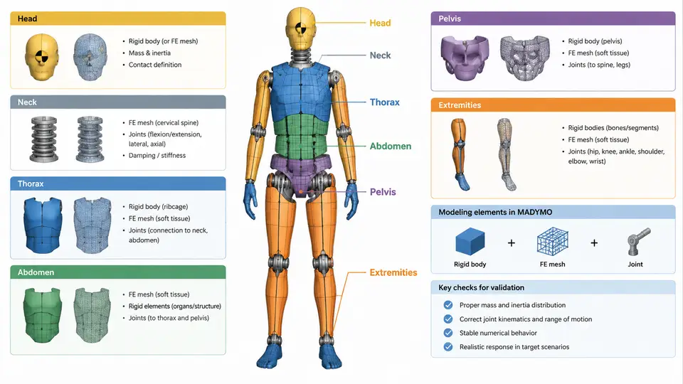
A MADYMO crash test dummy model is not a single monolithic object. It is an assembly of dozens of bodies connected by kinematic joints, with selected regions refined by finite element meshes. Understanding how the head, neck, thorax, abdomen, pelvis, and extremities are each represented — and why a particular representation is chosen — is the foundation of both model building and validation. This section walks through each major body region, the modeling technique typically applied, and the practical parameters that control behavior.
3.1 The Modeling Toolkit: Three Representations
MADYMO offers three fundamental ways to represent a dummy component, and most body regions use a combination of all three:
- Rigid bodies — defined by mass, center of gravity, and inertia tensor. They carry no deformation but provide the kinematic skeleton and inertial loading. A rigid body is the natural choice when the component's internal deformation is negligible compared to its gross motion, or when validated lumped compliance is sufficient.
- FE meshes — deformable shells or solids that capture local contact pressure, bending, and strain. They are used where injury criteria depend on distributed loading, such as chest deflection or facial bone fracture.
- Joints — kinematic constraints (revolute, spherical, translational, universal, free) that define allowed relative motion between bodies. Joints may include stiffness, damping, friction, and failure/rupture characteristics.
The choice is driven by the validation target. If the requirement is to match a corridor of head acceleration, a rigid head with correct mass and inertia is often sufficient. If the requirement is to predict skull fracture or facial contact force distribution, an FE head is necessary.
3.2 Head
The head is typically modeled as a single rigid body with mass around 4.5–5.0 kg for a 50th percentile male, a center of gravity located slightly forward and above the geometric center, and a diagonal inertia tensor. The head connects to the neck via a spherical or universal joint at the occipital condyle location. In more detailed models, the head is split into a rigid skull shell and an FE brain or facial structure, but for most restraint-system validation work the rigid head is preferred because it is computationally efficient and its inertial response is well characterized.
Key parameters to verify: head mass, moment of inertia about the lateral axis (typically 0.02–0.03 kg·m²), and the location of the head CG relative to the neck joint. An error of 10 mm in CG location can shift the measured head acceleration by several g's in a frontal impact.
3.3 Neck
The neck is the most challenging region to model because it must reproduce complex bending, tension, and shear behavior. MADYMO dummies typically use a multi-segment approach: several rigid bodies connected by revolute or spherical joints, each with nonlinear stiffness and damping. The neck joint stiffness is defined by moment-rotation curves derived from pendulum tests. A common configuration uses three or four segments to capture the S-shaped bending that occurs during whiplash.
Joint stops and rupture criteria are important. If the neck is allowed to hyperextend beyond physiological limits without a stop, the model will produce unrealistic kinematics. A typical neck model includes:
- Flexion/extension stiffness curves (moment vs. angle)
- Axial tension and compression stiffness
- Shear stiffness in anterior-posterior and lateral directions
- Damping coefficients to dissipate energy during dynamic loading
3.4 Thorax
The thorax is where FE meshes become essential. A rigid thorax cannot predict chest deflection, which is the primary injury criterion for frontal impact (e.g., 63 mm deflection for a 50th percentile male). The standard approach is a hybrid: a rigid spine and sternum connected by deformable FE ribs, or a full FE thorax with shell elements for ribs and solid elements for internal organs.
In MADYMO, the thorax is often modeled as a rigid body with a compliant joint at the spine and a set of FE ribs attached to the sternum. The rib material properties (elastic modulus, yield stress) are calibrated against cadaveric chest deflection tests. The thorax also includes a damping element to represent soft tissue. For side impact, the thorax model must capture lateral deflection and rib fracture, which requires a more detailed FE mesh with contact definitions between ribs and internal organs.
3.5 Abdomen
The abdomen is typically represented as a rigid body with a compliant joint or as a deformable FE region. Its primary role is to transfer loads from the pelvis to the thorax and to provide a contact surface for the seat belt. In frontal impact, the abdomen experiences compression from the belt; in side impact, it is loaded by the door. A common modeling approach is a rigid abdominal body with a nonlinear spring-damper element that allows compression up to a defined limit, beyond which the joint locks or ruptures.
3.6 Pelvis
The pelvis is a rigid body in most dummy models, with mass around 10–12 kg for a 50th percentile male. It connects to the lumbar spine via a spherical or universal joint and to the femurs via hip joints. The pelvis is the primary load path for the seat belt in frontal impact, so its geometry and contact stiffness must be accurate. In MADYMO, the pelvis is often modeled as a rigid body with an FE skin or contact surface to capture belt-pelvis interaction. The hip joints are typically revolute joints with stiffness and damping to represent the hip capsule.
3.7 Extremities
Arms and legs are usually modeled as rigid bodies connected by revolute joints at the shoulder, elbow, hip, and knee. The joints include stiffness and damping to represent muscle and ligament behavior. For pedestrian protection or occupant kinematics, the extremities may be modeled with FE meshes to capture fracture, but for restraint system validation, rigid bodies with appropriate joint properties are sufficient. The knee joint, for example, is often a revolute joint with a moment-rotation curve that allows flexion but resists hyperextension.
3.8 Putting It Together: A Component Map
The following diagram shows the typical MADYMO dummy architecture, indicating which regions use rigid bodies, which use FE meshes, and where joints connect them. This is not a flowchart of a process but a structural map of the model itself.
3.9 Practical Calibration Checks
After assembling the component model, three checks should be performed before running a full validation:
- Mass and inertia audit. Sum the masses of all rigid bodies and compare to the target dummy total mass (e.g., 78 kg for a 50th percentile male). Verify that the global CG location matches the published dummy specification within a few millimeters.
- Joint range-of-motion test. Apply a slow rotation to each joint and confirm that the moment-rotation curve matches the intended stiffness. A common error is a sign convention mismatch: a positive rotation that should produce flexion may instead produce extension if the joint axis is reversed.
- FE mesh quality check. For deformable regions, verify that the mesh has no negative Jacobians, that contact surfaces are properly defined, and that the time step is stable. A typical FE thorax model may require a time step of 1–2 microseconds, which is significantly smaller than the rigid-body time step.
3.10 Summary
Each dummy component has a preferred modeling strategy: the head and pelvis are predominantly rigid bodies, the neck uses multi-segment rigid bodies with nonlinear joints, the thorax combines a rigid spine with FE ribs, the abdomen uses a rigid body with a compliant element, and the extremities are rigid bodies with revolute joints. The art of dummy modeling lies in selecting the right representation for each region and calibrating the joint properties and FE material parameters against physical test data. The next section will address how these components are assembled into a complete dummy model and how the model is validated against certification corridors.