1. Introduction to MADYMO and crash test du
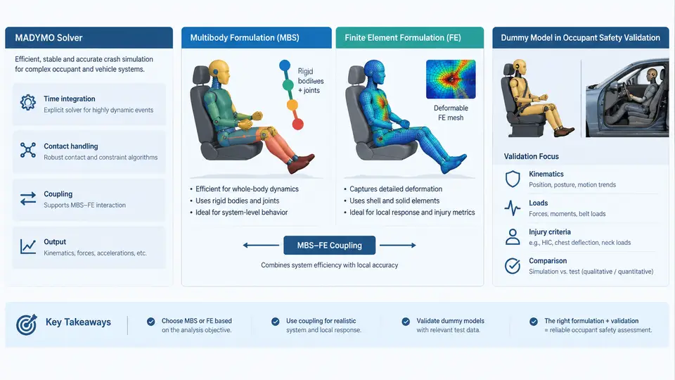
MADYMO (Mathematical Dynamic Model) is a commercial multi-body and finite element (FE) solver developed by TASS International (now part of Siemens) and widely used in the automotive industry for occupant safety analysis. Its core strength lies in the ability to simulate the kinematic and kinetic response of crash test dummies inside a vehicle environment during a crash pulse, providing engineers with a virtual test bench that complements and, in many cases, reduces the number of physical sled and full-vehicle tests. This chapter introduces the solver architecture, the two principal formulation families it offers, and the role dummy models play in occupant safety validation.
1.1 The MADYMO Solver at a Glance
MADYMO is a transient, explicit time-integration solver. A simulation is driven by a prescribed acceleration field (the crash pulse) applied to the vehicle body, while the occupant — represented by a dummy model — interacts with restraint systems (seat belts, airbags), interior surfaces, and the seat structure. The solver advances the system state in small time steps, typically on the order of 1 µs to 10 µs for FE-dominated models, and resolves contact, constraint, and joint forces at each step.
Two input languages are used in practice. The classic keyword-based input deck (often called the "MADYMO input file") defines bodies, joints, contacts, and loads in a structured text format. The newer MADYMO XML-based input, together with the Python-based madymo API and tools such as madymo_convert, supports parametric studies and automation. A minimal keyword snippet for a prescribed acceleration looks like this:
ACCELERATION
  ID      = 1
  BODY    = 100          ! vehicle body
  DIR     = Y
  FUNC    = 1            ! time-history function
  SCALE   = 1.0
END

FUNCTION
  ID      = 1
  TYPE    = TIME
  X       = 0.0, 0.02, 0.05, 0.08, 0.12
  Y       = 0.0, -15.0, -35.0, -20.0, 0.0   ! m/s^2 * 1e-3
END
Here the vehicle body (ID 100) receives a deceleration pulse along the global Y axis, defined by a time-function. The sign convention follows the MADYMO global coordinate system: +Y points forward in the vehicle, so a negative Y acceleration represents frontal deceleration. This convention must be stated explicitly and kept consistent throughout the model, because sign errors are one of the most common causes of unrealistic dummy kinematics.
1.2 Multibody versus Finite Element Formulations
MADYMO supports two complementary formulations, and most real dummy models combine both.
Multibody (MB) formulation. Rigid bodies are connected by kinematic joints (revolute, spherical, translational, universal, etc.). Each body has mass and inertia, and the joint degrees of freedom are solved together with contact and restraint forces. MB models are computationally cheap, numerically robust, and ideal for representing the dummy's articulated skeleton — pelvis, spine, thorax, neck, head, and limbs. A typical Hybrid III 50th percentile MB model contains roughly 30–40 bodies and 40–60 joints.
Finite element (FE) formulation. Deformable bodies are discretized into solid, shell, or membrane elements. FE is used where local deformation matters: the dummy's face and skull, the chest deflection, the abdomen, and the interaction between the dummy and an airbag. FE models are far more expensive and require careful mesh quality control, but they capture strain-rate effects and contact pressure distributions that MB cannot.
Coupled MB–FE. MADYMO allows an FE body to be attached to an MB body, or an FE airbag to interact with an MB dummy. This hybrid approach is the industry standard: the dummy skeleton is MB, while the airbag, belt webbing, and selected dummy components are FE.
1.3 The Role of Dummy Models in Occupant Safety Validation
Crash test dummies are physical instruments designed to measure human-like injury response. The Hybrid III family (50th, 5th percentile female, and 95th percentile male) remains the regulatory standard for frontal impact, while THOR and the WorldSID are used for advanced frontal and side impact research. A validated dummy model must reproduce the calibration corridors defined in the corresponding regulation — for example, the Hybrid III head drop test, the neck pendulum test, and the chest calibration test.
In a MADYMO study, the dummy model is placed in the vehicle environment, restrained, and subjected to the crash pulse. The solver outputs time histories of head acceleration, chest deflection, femur force, and the associated injury criteria (HIC, Nij, chest deflection, and so on). These outputs are compared against physical test data or regulatory limits. The validation loop therefore has three layers: (1) the dummy model itself must be validated against its calibration corridors; (2) the restraint and interior models must be validated against component tests; and (3) the full occupant model must be correlated against sled or vehicle tests.
The SVG below summarizes the data flow from crash pulse and restraint inputs through the coupled MB–FE dummy model to the injury criteria outputs, and shows where validation checkpoints are inserted.
1.4 A Minimal Worked Example
Consider a frontal sled simulation with a Hybrid III 50th percentile dummy. The steps below illustrate the typical workflow and the parameters you would actually set.
- Define the crash pulse. Load the sled acceleration time history into a
FUNCTIONobject and attach it to the vehicle body via anACCELERATIONentry. Verify the pulse by plotting the integrated velocity; the final velocity change (delta-v) should match the test specification, e.g. 56 km/h (15.6 m/s). - Position the dummy. Use the
INITIALblock to set the dummy's H-point and joint angles. A common error is a mismatch between the dummy's pelvis angle and the seat pan; this produces an unrealistic "submarining" motion. Check the initial belt-to-dummy gap, typically 0–5 mm. - Activate restraints. Define the belt as an FE membrane with a prescribed force–strain curve, and the airbag as an FE model with a
GASinflow function. Set the airbag trigger time, e.g. 15 ms after T0. - Run the solver. Set the time step to 1 µs for the FE airbag and 10 µs for the MB dummy, and enable
COUPLINGbetween the two. Monitor the energy balance; a growing hourglass or contact energy indicates a modeling problem. - Post-process. Extract head acceleration, chest deflection, and femur force. Compute HIC15 and compare against the regulatory limit (e.g. HIC ≤ 700 for a 50th percentile dummy in a frontal test).
1.5 Key Takeaways
- MADYMO is an explicit transient solver combining multibody and finite element formulations; most dummy models are hybrid MB–FE.
- The crash pulse, restraint models, and dummy model are the three primary inputs; the outputs are kinematic time histories and injury criteria.
- Validation is layered: dummy calibration, restraint component correlation, and full occupant correlation.
- Sign conventions, coordinate systems, and initial positioning must be defined explicitly and kept consistent; they are the most frequent source of unrealistic results.
- A staged modeling approach — MB first, then FE — isolates errors and keeps the simulation tractable.
With this foundation, subsequent chapters will examine the dummy model architecture in detail, the construction of restraint models, and the quantitative correlation methods used to validate a MADYMO occupant model against physical test data.