4. WorldSID sensor architecture
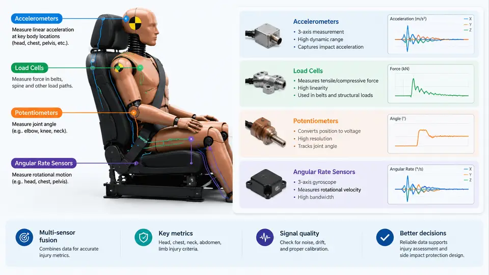
The WorldSID 50th percentile male dummy is not a single measurement device but a distributed instrumentation platform. Its injury-assessment capability depends on four distinct sensor families working together: accelerometers that capture rigid-body and segment kinematics, load cells that resolve forces and moments at structural interfaces, potentiometers that track relative displacement and rotation across joints, and angular rate sensors that measure rotational velocity directly. Understanding which sensor answers which injury question — and how their signals are conditioned, filtered, and combined — is the foundation for every subsequent metric in this course, from HIC and BrIC to rib deflection and pelvic force.
The critical design principle is measurement at the injury site, not at the test frame. A barrier accelerometer tells you what the sled did; a WorldSID rib accelerometer tells you what the occupant's chest experienced. Every sensor in the dummy is placed to close that gap between the external loading environment and the internal biomechanical response.
Accelerometers: Segment Kinematics and Head/Brain Metrics
WorldSID uses triaxial piezoelectric or piezoresistive accelerometers at the head CG, upper and lower ribcage, pelvis, and — in some configurations — the spine box and femur. Each channel is a full three-axis set, so a single head location yields Ax, Ay, Az in the dummy's local coordinate system. The SAE J211 convention applies: the dummy's forward direction is +X, left is +Y, and up is +Z, with the origin at the dummy's anatomical reference point. All acceleration channels are signed against this frame, and any post-processing must preserve it.
Head acceleration drives two metrics. The resultant acceleration a_r = √(Ax² + Ay² + Az²) feeds HIC36/HIC15 through the standard integral over the critical time window. For side impact specifically, the rotational components matter more: the angular acceleration derived from paired accelerometers (or from the angular rate sensor, below) feeds BrIC, which combines peak angular velocity about the three axes. A practical point: raw accelerometer data must be filtered per SAE J211 Channel Frequency Class — CFC 1000 for head acceleration, CFC 180 or CFC 600 for chest and pelvis depending on the metric — before any metric is computed. Applying the wrong CFC class silently shifts HIC and BrIC values by several percent.
Chest accelerometers serve a different purpose: they are not primarily injury metrics themselves but inputs to rib deflection and viscous criterion calculations when combined with potentiometer data, and they provide the upper/lower chest acceleration traces used in chest acceleration criteria (a 3 ms clip concept). Pelvis accelerometers feed pelvic acceleration limits and, together with pubic symphysis load cells, complete the pelvic injury picture.
Load Cells: Interface Forces and Moments
Where accelerometers measure motion, load cells measure the forces transmitted across structural interfaces. WorldSID carries several load cell types, each matched to a specific injury mechanism:
- Upper and lower rib load cells — measure the force transmitted through the rib modules into the spine box, giving a direct read on chest compression force.
- Pubic symphysis load cell — a multi-axis cell at the pelvis midline capturing the lateral force and moment associated with pelvic ring fracture.
- Iliac wing load cells — measure lateral loading at the pelvis wings, relevant to acetabular and iliac injury.
- Femur load cells — axial and bending loads at the proximal femur, used for femur fracture assessment.
- Shoulder and abdomen load cells — in configurations that instrument the shoulder joint and abdominal region.
Most WorldSID load cells are six-axis (Fx, Fy, Fz, Mx, My, Mz), though some locations use three-axis or single-axis cells. The output is a voltage proportional to strain, converted through a calibration matrix that decouples cross-axis sensitivity. A common pitfall in data reduction is applying the calibration matrix in the wrong order or using a matrix from a different build revision — the resulting force traces look plausible but are systematically offset. Always verify the cell serial number against the calibration certificate before processing.
Potentiometers: Deflection and Joint Rotation
Rib deflection is the signature WorldSID measurement, and it is captured by potentiometers — linear or rotary — mounted across the rib modules. As the chest is compressed laterally, the potentiometer wiper moves and produces a resistance change proportional to displacement. The chest deflection metric is the peak of this displacement, and the viscous criterion VC = 1.3 × V × C (where V is the instantaneous compression velocity and C the normalized compression) is derived by differentiating the deflection trace.
Potentiometers also instrument joints: the neck, shoulder, and in some builds the lumbar spine, providing relative rotation angles. These are essential for validating that the dummy's posture during the impact matches the intended loading configuration — a shoulder potentiometer reading that exceeds its expected range often indicates the arm was not positioned correctly before the test, which invalidates the run.
Two practical cautions apply. First, potentiometers are ratiometric devices; the excitation voltage must be stable and recorded, because a drifting supply corrupts the displacement scale. Second, mechanical end-stops protect the wiper, but a hard bottoming-out during a severe impact produces a clipped, flat-topped trace — this is a saturation event, not a real deflection plateau, and must be flagged in the test report.
Angular Rate Sensors: Direct Rotational Measurement
Angular rate sensors (gyroscopes) are mounted at the head and, in some configurations, the chest and pelvis. They measure angular velocity directly in deg/s about each axis, avoiding the numerical differentiation and noise amplification that plagues acceleration-derived rotation. For BrIC, the head angular velocity about the three axes is the primary input, and a dedicated gyro channel gives a cleaner signal than differentiating paired accelerometers.
The trade-off is drift and bandwidth. MEMS gyros exhibit bias drift that must be characterized and, where possible, compensated; the sensor's bandwidth must also cover the frequency content of the impact — a gyro with insufficient bandwidth will underestimate peak angular velocity and therefore under-report BrIC. During setup, confirm the gyro's range setting matches the expected impact severity; a range that is too low will clip, and one that is too high sacrifices resolution.
How the Channels Combine
The four sensor families are not independent — they are fused into injury metrics. The diagram below shows the signal chain from physical sensor to metric for the principal WorldSID channels, including the filtering and coordinate conventions that must be applied consistently.
Two fusion relationships deserve emphasis. First, rib deflection and chest acceleration are complementary: deflection captures the structural compression of the ribcage, while acceleration captures the inertial response of the chest mass. Neither alone fully characterizes chest injury risk, and the two traces should be reviewed together — a high deflection with modest acceleration suggests a quasi-static crush, while the reverse suggests a sharp inertial loading. Second, head acceleration and head angular rate jointly determine the rotational injury picture: HIC captures translational severity, BrIC captures rotational severity, and a test that passes one may still fail the other.
Practical Data-Reduction Workflow
A reproducible reduction sequence for a WorldSID side-impact test looks like this. Begin by confirming the dummy build and sensor serial numbers against the calibration database, then verify the zero offsets recorded before the run. Apply the correct CFC filter per channel class — CFC 1000 for head acceleration and gyro, CFC 600 for chest/pelvis acceleration and load cells, CFC 600 for rib deflection. Transform all channels into the SAE J211 dummy frame, checking that the sign of lateral acceleration is consistent with the impact direction. Compute the metrics: HIC over the 36 ms and 15 ms windows, BrIC from peak angular velocities, peak rib deflection and VC, and peak forces at each load cell. Finally, cross-check for saturation, drift, and clipping before accepting any value.
With the sensor architecture understood at this level — what each family measures, how it is conditioned, and how the channels fuse into metrics — the next layer of work becomes tractable: interpreting the resulting numbers against injury thresholds and using them to evaluate protective countermeasures. The architecture is the measurement foundation; the metrics are the engineering language built on top of it.