4. Dummy positioning and pre-test setup
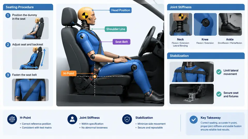
In a frontal sled or crash test with the THOR-M dummy, the validity of every subsequent measurement — head acceleration, chest deflection, femur load, restraint forces — depends on how the dummy was seated before the run. A dummy that sits 15 mm too high, leans 2° too far forward, or has a knee joint that settles during the acceleration pulse will produce data that looks plausible but is not comparable to the reference corridor. Positioning is therefore a controlled, documented procedure, not a rough placement. This section walks through the seating sequence, the role of the H-point, joint stiffness management, and the stabilization steps that must be completed before the test is armed.
Why the H-point anchors everything
The H-point (hip point) is the physical location of the dummy's hip joint center relative to the seat and the vehicle coordinate system. In THOR-M, the H-point is defined by the dummy's internal structure and is measured or referenced through the H-point backset and height relative to the seat. The seat reference point (SRP) and the actual H-point of the seated dummy should coincide within a defined tolerance — typically ±10 mm in height and ±10 mm in longitudinal position for a well-prepared test, with tighter targets (±5 mm) used when comparing against a certified reference setup.
The reason this matters is geometric: the H-point sets the pelvis orientation, which in turn sets the spine curve, the shoulder position, and therefore the belt routing across the chest and lap. A 10 mm H-point error can shift the shoulder belt anchor path by a comparable amount and change chest deflection readings by several millimeters. Before any joint is adjusted, confirm the seat is at its specified position (seat track, cushion angle, backrest angle) and that the seat is locked. Record the seat position values; they are part of the test record.
Seating procedure
The seating sequence follows a deliberate order so that each adjustment does not disturb the previous one. A practical sequence for THOR-M is:
- Place the dummy in the seat with the pelvis centered on the cushion and the back against the backrest. Do not yet fasten the belt.
- Set the pelvis and H-point by sliding the dummy rearward until the pelvis contacts the backrest, then verify H-point height and longitudinal position against the target using the H-point measurement fixture or the dummy's built-in reference marks.
- Adjust the torso so the spine follows the backrest contour; check that the chest is not twisted relative to the pelvis.
- Set the head to the specified head angle (often defined relative to the vehicle vertical or the torso) and confirm the head-to-headrest gap.
- Position the limbs — arms on the steering wheel or at the specified arm angle, legs with the specified knee angle and foot placement on the pedals or floor.
- Route and fasten the belt last, so belt tension does not pull the dummy out of position before the joints are set.
Each step should be verified, not assumed. A common error is to fasten the belt early; the retractor preload then drags the torso forward or sideways and silently invalidates the H-point.
Joint stiffness: the part that moves after you let go
THOR-M joints are not rigid. The neck, shoulder, elbow, hip, knee, and ankle joints have defined stiffness and damping so the dummy behaves like a human during the crash pulse. That same compliance means the dummy can settle after you position it. Joint stiffness must be set to the specification for the test configuration — typically a torque or resistance value per joint — and then checked. If a joint is too loose, the limb droops between setup and the run; if too tight, the limb does not respond realistically during the pulse and can bias loads.
Practical checks: apply the specified setting torque to each adjustable joint, then release and observe. A knee that continues to fall under its own weight after release indicates insufficient stiffness or a worn joint. Record the joint settings in the setup sheet. For the neck especially, the setting affects head kinematics and must match the configuration called out in the test plan.
Stabilization before the run
Stabilization is the period between final positioning and test release during which the dummy is allowed to settle and the setup is confirmed stable. The goal is to ensure the dummy does not drift, sag, or creep once the belt is tensioned and the test is armed. A typical stabilization check includes:
- Re-verify H-point after belt fastening; it should remain within tolerance.
- Confirm joint positions have not changed (mark or photograph reference points).
- Check belt routing and tension against the specified value.
- Allow a defined settling interval (commonly 30–60 s) and re-check for movement.
- Record ambient temperature, since foam and belt material properties are temperature-sensitive.
If the dummy moves during stabilization, do not simply re-push it into place — find which joint or contact is allowing the drift and correct the setting. Pushing a settled dummy back into position without fixing the cause usually means it will drift again during the pulse.
Worked example: a setup that drifts
Consider a sled test where the dummy is positioned, the belt is fastened, and the H-point is re-checked at 12 mm high — just outside a ±10 mm tolerance. The technician pushes the pelvis down and re-checks: now 8 mm, within tolerance. The test proceeds. During the pulse, the dummy's pelvis rotates earlier than the reference data predicts, and chest deflection is low. The likely cause is that the pelvis was never properly seated on the cushion; pushing it down compressed the cushion temporarily, and the joint or cushion recovered during the run. The correct response at setup would have been to release the belt, re-seat the pelvis, confirm the cushion is not being artificially compressed, and re-run the stabilization check. The lesson: a position that only holds while you are pressing on it is not a stable position.
Setup record
Every positioning decision should be captured in a setup sheet so the test is reproducible and any anomaly can be traced. A minimal record for this stage includes:
| Item | Recorded value | Acceptance |
|---|---|---|
| Seat track / cushion / backrest | Position values | Match test plan |
| H-point height | mm from SRP | Within ±10 mm (±5 mm ref.) |
| H-point longitudinal | mm from SRP | Within ±10 mm (±5 mm ref.) |
| Head angle | degrees | Per configuration |
| Joint settings | Neck, shoulder, elbow, hip, knee, ankle | Per specification |
| Belt tension | N | Per specification |
| Stabilization drift | mm over interval | No measurable drift |
| Ambient temperature | °C | Within test window |
The setup is complete only when the H-point, joint settings, belt routing, and stabilization check all pass together. If any one of them fails, correct the cause and repeat the affected checks — do not carry a known deviation into the run and hope the data will be usable. A clean, documented setup is what makes the THOR-M measurements comparable to the reference corridor and defensible in the test report.