4. Steering column architecture
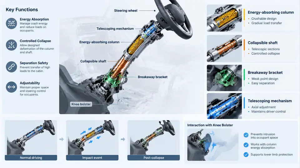
The steering column is the primary load path between the driver and the vehicle structure during a frontal impact. Its architecture must satisfy two conflicting requirements: transmit steering torque with minimal compliance and backlash during normal driving, yet deform in a controlled, repeatable manner when the driver's torso loads the steering wheel through the airbag. This chapter examines the four structural subsystems that resolve this conflict — the energy-absorbing column, the collapsible intermediate shaft, the breakaway mounting bracket, and the telescoping mechanism — and how they interact as a single crash load path.
Load Path and Design Intent
In a frontal impact, the driver moves forward relative to the vehicle as the restraint system and belt pay out. The steering wheel, mounted on the column, becomes a potential hard contact point for the chest and head. The column's job is to allow the wheel to translate forward (toward the dash) while absorbing a defined amount of energy, so that the occupant's deceleration stays within tolerable limits and the wheel does not intrude into the occupant's survival space. The design target is usually expressed as a force–displacement corridor: a minimum force to prevent the column from collapsing under normal hand loads, and a maximum force to keep chest loading acceptable, with a total stroke sufficient to clear the occupant's forward excursion.
Three reference conventions are used throughout this chapter. Forward means toward the front of the vehicle (the direction of travel). Column axis is the steering shaft centerline, inclined at the design rake angle. Stroke is measured along the column axis, positive in the forward direction. All force values are axial unless stated otherwise.
Energy-Absorbing Column
The energy absorber converts kinetic energy into plastic work as the column shortens. The most common production solution is a deformable metal strap or tube that is drawn through a die or rolled over a mandrel as the upper column jacket slides into the lower jacket. The force level is set by material grade, strap thickness, and die radius. A second common architecture uses crushable steel or aluminum tubes with controlled folding initiators, and a third uses friction-based absorbers where a calibrated interference fit provides a near-constant drag force.
The key design parameter is the mean crush force and its stroke. For a target chest load, engineers size the absorber so that the force stays inside the corridor across the full stroke. A representative example (illustrative, not measured): a column designed for a 60 mm stroke with a mean axial force of 3.5 kN absorbs roughly 210 J. If the occupant's forward excursion at the wheel is 55 mm, the absorber must be fully engaged before that point and must not bottom out, or the force will spike and the corridor will be violated.
Collapsible Intermediate Shaft
Between the column and the steering gear sits the intermediate shaft, which must telescope or collapse axially during the crash while still transmitting steering torque. Two families dominate: sliding spline shafts with a plastic or nylon shear sleeve, and collapsible tube-and-rod designs where the rod is press-fit into the tube and is pushed out under axial load. The spline version is common because it also accommodates build variation and steering system runout.
The critical behavior is the slip force: the axial force required to overcome the spline friction and shear features. It must be low enough not to add to the column's crash force, but high enough that normal steering torque and road feedback do not cause slip. A typical design uses a shear pin or a crimped sleeve calibrated to a slip force of 1–2 kN, well below the column absorber's 3.5 kN, so the shaft collapses first and the absorber then takes over. The shaft must also retain torque capacity after slip — a spline that has slid 40 mm must still transmit the full steering torque without binding.
Breakaway Bracket
The column is attached to the vehicle body (typically the instrument panel cross-car beam and the floor or lower dash) through a mounting bracket. In a crash, this bracket must release in a controlled way so the entire column can translate forward. The release is achieved by shear tabs, breakaway bolts, or a frangible die-cast feature designed to fail at a defined load. The bracket's breakaway force is set slightly above the maximum normal operating load (driver pulling on the wheel, column adjustment loads) and below the level that would cause occupant injury.
A practical design sequence is: (1) define the maximum normal load, including a driver using the wheel for support during entry/exit, typically 0.5–1.0 kN; (2) set the breakaway threshold at 1.5–2.0× that value; (3) confirm the bracket releases before the absorber reaches its force plateau, so the column is free to stroke. If the bracket releases too late, the column cannot translate and the absorber is bypassed — the wheel becomes a rigid intrusion. If it releases too early, the column may feel loose or rattle during normal driving.
Telescoping Mechanism
The telescoping mechanism provides the axial stroke that the absorber and bracket enable. It is usually a telescoping jacket pair: an upper jacket that slides inside a lower jacket, with a low-friction liner or a controlled interference to keep steering feel tight. The mechanism must provide a defined stroke (commonly 50–80 mm in passenger cars) and must not bind or cock under the off-axis loads that occur when the driver loads the wheel asymmetrically. A common failure mode is jacket binding when the column is loaded at an angle, which raises the effective force and violates the corridor. Designers address this with generous overlap length, a guide bushing, and a clearance that tolerates the expected angular misalignment.
Integration: How the Four Subsystems Cooperate
The subsystems are not independent; they form a sequenced load path. During a frontal impact the sequence is typically: the breakaway bracket releases first (lowest force threshold), the intermediate shaft slips or collapses, the telescoping jacket begins to stroke, and the energy absorber provides the controlled force plateau over the remaining stroke. The design must ensure the thresholds are ordered correctly — bracket release < shaft slip < absorber plateau — otherwise one component will block another and the corridor will be violated.
A useful verification approach is a quasi-static column crush test on a servo-hydraulic rig, pushing the wheel hub axially at 50–100 mm/min while recording force and displacement. The resulting curve should show a clean release event, a stable plateau within the corridor, and no force spike at end of stroke. A force spike at the start indicates bracket or shaft binding; a plateau above the corridor indicates an over-stiff absorber or jacket interference; a plateau below the corridor indicates insufficient energy absorption and a risk of bottoming out.
| Subsystem | Primary function | Typical design parameter | Failure symptom |
|---|---|---|---|
| Energy absorber | Dissipate energy over stroke | Mean force 3–4 kN, stroke 50–80 mm | Force spike at end of stroke; corridor violation |
| Collapsible shaft | Allow axial collapse, retain torque | Slip force 1–2 kN | Binding after slip; torque loss |
| Breakaway bracket | Release column at defined load | Release 1.5–2.0 kN | Late release blocks stroke; early release causes rattle |
| Telescoping jacket | Provide guided axial stroke | Stroke 50–80 mm, controlled clearance | Jacket binding under off-axis load |
The practical takeaway is that column crash performance is a system-level tuning problem. Each subsystem has a narrow force window, and the windows must be ordered and non-overlapping. When a column fails a sled or crush test, the first diagnostic step is to plot the force–displacement curve and identify which event — release, slip, or plateau — is out of position, then adjust only that subsystem and re-test the assembly.