1. Frontal occupant protection system overv
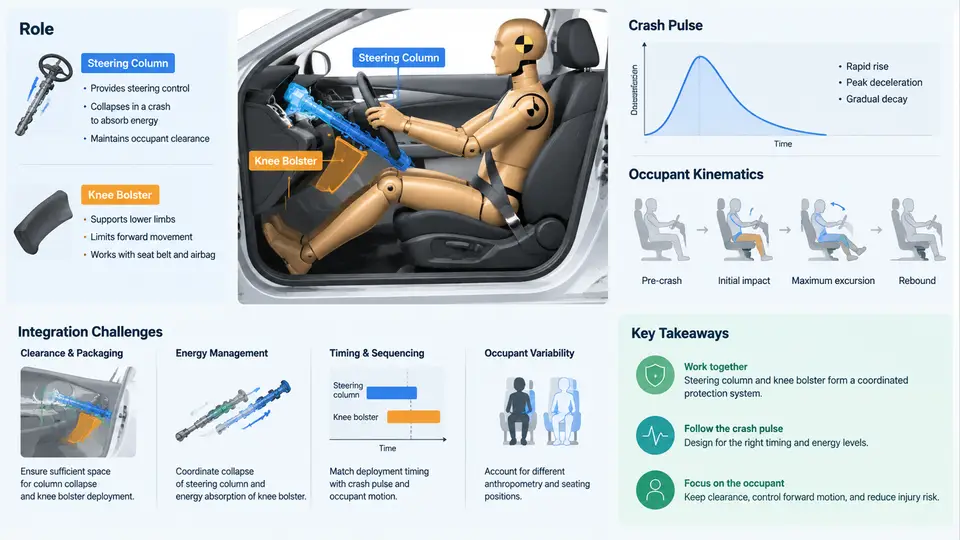
Frontal occupant protection is a system-level engineering problem, not a collection of individually optimized parts. The steering column and the knee bolster sit at the two most consequential interfaces between the occupant and the vehicle interior during a frontal impact: the upper body loads the column through the airbag and the chest, while the lower extremities load the bolster through the knees and femurs. Understanding how these two subsystems share the crash energy, and how the crash pulse and occupant kinematics determine when and where that energy arrives, is the foundation for every integration decision that follows in this course.
The Restraint System as an Energy-Management Chain
In a frontal crash, the vehicle's front structure decelerates the occupant compartment over a finite distance and time. The occupant, restrained primarily by the seat belt and airbag, continues forward relative to the compartment. The restraint system's job is to couple the occupant to that deceleration as gently and as early as possible, keeping loads within injury-tolerance corridors defined by criteria such as HIC15 for the head, chest deflection and 3 ms clip for the thorax, and femur axial force and knee displacement for the lower extremities.
The steering column and knee bolster are the two structural load paths that complement the belt and airbag:
- Steering column. In a belted frontal impact, the driver's chest and head interact with the airbag, which is supported by the column. The column must be stiff enough to react the airbag's deployment and loading forces so the bag can manage head excursion, yet it must collapse in a controlled axial stroke when the driver's chest loads it, absorbing energy and limiting chest compression. Column stroke, breakaway force, and energy-absorption (EA) characteristics are therefore tuned together with airbag venting and belt load limiting.
- Knee bolster. The bolster is the primary lower-extremity load path. It limits forward femur travel, controls knee trajectory to keep the femurs loading the bolster rather than submarining under the instrument panel, and absorbs energy through controlled deformation. It also indirectly influences pelvis kinematics and, in unbelted or out-of-position cases, can be the dominant lower-body restraint.
Neither subsystem can be tuned in isolation. A stiffer column raises chest loading but may reduce head excursion; a softer bolster lowers femur force but allows greater knee travel and can change pelvis pitch, which in turn alters chest-to-airbag alignment. Integration is the discipline of resolving these trade-offs against a common occupant response target.
Crash Pulse and Occupant Kinematics
The crash pulse is the deceleration-time history of the occupant compartment (or a specified structural point) during impact. It is the input that drives everything downstream. Two pulses with the same velocity change (delta-v) but different shapes produce very different occupant responses: a short, high-amplitude pulse delivers energy quickly and demands early restraint coupling, while a longer, lower-amplitude pulse allows more occupant ride-down but greater forward excursion.
For integration work, the pulse is usually characterized by its delta-v, peak deceleration, duration, and the time at which the occupant begins to load each restraint. A representative 56 km/h frontal barrier pulse might show a delta-v near 15–16 m/s with a peak compartment deceleration in the 35–45 g range and a duration of roughly 90–120 ms; these are illustrative values for teaching, not measured results. The occupant's forward excursion relative to the compartment typically begins to load the belt within the first 20–30 ms, the airbag within 30–50 ms, and the knee bolster shortly after as the pelvis rotates and the knees drive forward.
Occupant kinematics in a frontal impact follow a recognizable sequence: the pelvis is restrained by the lap belt and begins to rotate forward; the torso loads the shoulder belt and airbag; the head moves forward and downward into the bag; the knees and femurs translate forward toward the bolster. The timing of these events relative to the pulse determines which restraint is doing work at which moment. If the bolster is engaged too early, it can stiffen the lower-body path and raise femur loads; if too late, the knees travel too far and may strike the instrument panel structure or promote submarining.
Integration Challenges
The practical difficulty is that the column and bolster are developed by different teams, validated against different load cases, and packaged in a shared, tightly constrained space. The most common integration challenges are:
- Load-path competition. Column EA and bolster crush both draw on the same occupant kinetic energy. Over-tuning one shifts load to the other and can push chest or femur metrics out of corridor.
- Packaging and stroke. Column stroke is limited by the instrument panel and firewall; bolster crush depth is limited by HVAC and electrical components. Available stroke directly caps achievable EA.
- Out-of-position and unbelted cases. A bolster tuned for a belted 50th-percentile occupant may be too stiff for a small occupant or too soft for an unbelted large occupant. Column breakaway force must also avoid injurious loading in OOP deployments.
- Geometry and alignment. Knee-to-bolster contact location, column tilt/telescope position, and airbag module geometry all interact. A 20 mm shift in bolster surface can change knee loading direction and femur force significantly.
- Variability. Occupant size, seating position, belt use, and pulse variation all move the operating point. Robust integration targets the corridor, not a single nominal response.
What "Good Integration" Looks Like in Practice
A well-integrated frontal protection system produces occupant responses that sit comfortably inside the injury corridors across the validation matrix, not just at the nominal 50th-percentile belted condition. In practice, engineers evaluate this by running a matrix of sled or full-vehicle tests (or validated CAE models) covering small, mid-size, and large occupants, belted and unbelted, at multiple seat positions, against the applicable pulse family. The column and bolster are then adjusted iteratively: column EA force and stroke are traded against bolster crush force and depth until the chest, head, and femur metrics all have margin.
A concrete way to frame the trade study is to treat the two subsystems as parallel energy absorbers sharing the occupant's forward kinetic energy. If the column absorbs too much, chest loading rises; if the bolster absorbs too much, femur force and knee travel rise. The integration target is the split that keeps both within corridor while preserving head excursion margin. This is why the column and bolster cannot be signed off independently, and why the crash pulse and occupant kinematics must be agreed upon as the common reference before either subsystem is tuned.
The remainder of this course builds on this foundation: subsequent chapters examine column energy-absorption design, bolster geometry and crush behavior, the CAE and test methods used to evaluate them, and the validation and sign-off process that demonstrates the integrated system meets its occupant-protection targets.