4. Occupant packaging and interior design c
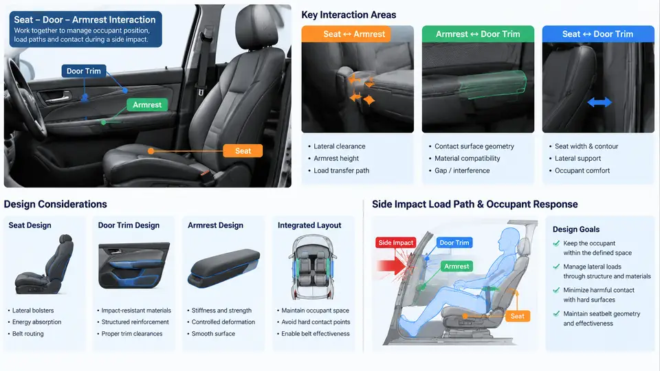
Side impact protection is fundamentally a packaging problem before it is a restraint problem. The lateral distance between the occupant's outboard shoulder/thorax and the intruding door structure is measured in tens of millimeters, and every millimeter of that gap is contested by seat bolster geometry, armrest position, door trim thickness, and the hardware hidden behind the trim. This chapter examines how seat design, door trim architecture, and armrest interactions determine the available "survival space" and how restraint performance (side airbags, thorax/pelvis airbags, curtain airbags) depends on that space being preserved and predictable.
Defining the Reference Frame and Key Packaging Dimensions
Before discussing geometry, establish a consistent reference convention. All lateral dimensions in this chapter are expressed in the vehicle coordinate system: Y is positive toward the vehicle's right side, origin at the vehicle centerline; X is positive forward; Z is positive upward from the ground plane. Occupant outboard surfaces are therefore at negative Y for a left-hand-drive driver (left side) and positive Y for the right side. When we say "clearance," we mean the minimum Y-distance between the occupant's compressed outboard surface (as defined by the dummy or H-point manikin) and the nearest rigid interior or structural surface at the moment of peak intrusion.
Three packaging dimensions dominate side impact outcomes:
- D1 — Thorax-to-door clearance: lateral gap between the 50th percentile occupant's outboard thorax and the door trim inner surface at the armrest/bolster height (typically Z ≈ 550–650 mm above ground).
- D2 — Pelvis-to-door clearance: gap at the H-point height (Z ≈ 250–350 mm), strongly influenced by seat cushion side bolster and door sill/armrest lower geometry.
- D3 — Head-to-curtain clearance: gap between the occupant's head and the roof rail/curtain airbag module, which governs curtain deployment timing and coverage.
In a typical B-segment passenger car, D1 at the driver's outboard thorax is often only 80–120 mm in the undeformed condition. Under a 50 km/h MDB (moving deformable barrier, ECE R95 / FMVSS 214-style) impact, door intrusion at the occupant compartment can consume 60–100 mm of that gap within the first 40–60 ms. The restraint system must therefore deploy into a rapidly shrinking space — which is why packaging decisions made years before the airbag calibration directly cap achievable performance.
Seat Design: Bolsters, Frames, and the Outboard Boundary
The seat is not a passive occupant support in side impact; it is the primary lateral locator. The outboard side bolster of the seat backrest sets the occupant's lateral position and thus D1. A deep, aggressive bolster (common in sport seats) can reduce D1 by 15–25 mm compared with a flat touring seat, because it pushes the occupant inboard relative to the door. This is generally favorable for clearance but introduces a trade-off: a stiff bolster can act as a load path that concentrates force into the occupant's lower ribs during intrusion, and it can interfere with side airbag deployment if the airbag module is seat-mounted.
Seat-mounted side airbags (SABs) are the dominant architecture in modern vehicles. The module is packaged in the outboard side of the backrest, typically between the bolster foam and the seat frame, with a tear seam in the trim cover. Key packaging constraints:
- Module-to-frame clearance: the inflator and folded cushion must not be pinched by the seat frame or recliner mechanism; a minimum of 8–12 mm clearance to rigid frame members is a common design guideline to avoid deployment restriction.
- Tear seam location: must align with the airbag's deployment trajectory, typically 30–50 mm below the bolster crown, and must not be obstructed by the occupant's arm or by the armrest.
- Seat frame stiffness: the outboard frame rail and recliner must withstand the reaction force of the deploying airbag (several kN) without permanent deformation that would misdirect the cushion.
Seat cushion side bolsters also matter for pelvis control. A taller, firmer outboard cushion bolster reduces lateral pelvis excursion during intrusion, keeping the pelvis away from the door's lower structure and improving the alignment between the pelvis and a seat-mounted pelvis airbag. However, excessive bolster height can make ingress/egress difficult and can interfere with the seat belt buckle presentation — a packaging compromise that must be resolved early in the interior design freeze.
Door Trim Architecture and Intrusion Management
The door trim is the occupant-facing surface of the intruding structure. Its design determines both how much energy is absorbed before the occupant is loaded and how the load is distributed. A typical side door trim assembly comprises: the trim substrate (PP or PP-GF), a foam or energy-absorbing pad, the armrest/bolster, the map pocket, and the inner door panel with its intrusion beam and beltline reinforcement.
Energy-absorbing (EA) pads behind the trim substrate are the primary countermeasure. A well-designed EA pad — typically expanded polypropylene (EPP) or a ribbed injection-molded structure — can absorb 1.5–3 kJ of energy over 40–60 mm of stroke, reducing peak force transmitted to the occupant's thorax. The pad's crush characteristic must be tuned to the intrusion velocity: too stiff and it transmits high force early; too soft and it bottoms out before the intrusion is arrested, leaving the occupant loaded by the rigid door structure.
The trim substrate itself must be designed to fail predictably. Sharp edges, hard attachment points (screws, clips), and stiff map pocket rims are common sources of occupant injury in side impact. Design guidance includes: recessing or covering all fasteners, using rounded radii (≥ 5 mm) on occupant-contact surfaces, and avoiding rigid protrusions within the occupant's lateral excursion envelope.
Armrest Interactions: The Critical Interface
The armrest is the single most consequential trim feature for side impact packaging, because it sits directly in the load path between the intruding door and the occupant's lower thorax/abdomen. Three interaction modes must be managed:
- Armrest as a load concentrator: a rigid armrest projecting 60–80 mm inboard from the door surface can concentrate intrusion force into a narrow band of the occupant's lower ribs. The fix is either to make the armrest collapsible (a crushable armrest with a designed collapse load of 1–2 kN) or to position it below the occupant's ribcage (Z below ~450 mm) so it loads the pelvis/hip rather than the thorax.
- Armrest as an airbag obstruction: if the armrest is positioned in the deployment path of a door-mounted or seat-mounted thorax airbag, it can deflect the cushion or cause the airbag to deploy behind the armrest, leaving the thorax unprotected. The armrest must be either below the airbag's deployment corridor or designed to break away cleanly.
- Armrest as an occupant-positioning feature: occupants frequently rest their outboard arm on the armrest, which moves the arm into the deployment path and can cause arm-to-airbag interaction injuries. Some OEMs use a "soft" armrest with a low breakaway threshold, and some restraint calibrations include arm-in-position sensing or dual-stage deployment to reduce injury risk.
The following diagram summarizes the packaging relationships and the load/deployment paths that connect seat, door trim, armrest, and restraint:
Integrating the Three Subsystems: A Packaging Review Workflow
The seat, door trim, and armrest are developed by different teams (seat supplier, interior trim supplier, body engineering) and are frequently frozen at different times. To avoid late-stage conflicts, a structured packaging review should be run at three gates:
| Gate | Timing | Key Checks | Typical Failure Mode |
|---|---|---|---|
| Concept | Before trim/seat styling freeze | D1/D2/D3 with 5th–95th percentile occupants; armrest height vs. ribcage; SAB module envelope | Armrest positioned in SAB deployment corridor |
| Design | After CAD release, before tooling | EA pad crush curve vs. intrusion velocity; tear seam alignment; fastener protrusion scan | EA pad bottoms out before intrusion arrested |
| Validation | Prototype build | Sled test with door intrusion; arm-in-position variants; trim breakaway force measurement | Armrest deflects airbag; trim sharp edge contact |
At the concept gate, the most useful single artifact is a lateral cross-section at the occupant's thorax height, overlaid with the 5th and 95th percentile occupant profiles and the SAB folded envelope. This immediately reveals whether the armrest, bolster, or trim substrate intrudes into the deployment corridor. At the design gate, the EA pad's force–displacement curve should be compared against the predicted door intrusion velocity profile from the CAE side impact model; a pad that reaches its densification point before the intrusion peak is effectively rigid. At validation, a simple breakaway test — pulling the armrest outboard with a force gauge until it separates — confirms the designed collapse load and verifies that the breakaway does not leave a sharp attachment feature exposed.
Practical Takeaways
- Measure D1 and D2 at the worst-case seat position and with the largest occupant profile the restraint must protect; the restraint calibration is only as good as the clearance it deploys into.
- Treat the armrest as a structural element in the load path: give it a designed collapse load (typically 1–2 kN) and keep it out of the SAB deployment corridor, or make it break away cleanly.
- Tune the EA pad's crush characteristic to the intrusion velocity, not to a generic stiffness target; verify with the CAE intrusion profile before tooling.
- Run the three-gate packaging review with a shared lateral cross-section artifact so that seat, trim, and restraint teams are evaluating the same geometry.
When these packaging fundamentals are respected, the restraint system — seat-mounted thorax and pelvis airbags, curtain airbags, and belt pretensioners — deploys into a predictable, controlled space. When they are not, no amount of airbag calibration can recover the lost millimeters.