4. Finite element modeling for side impact
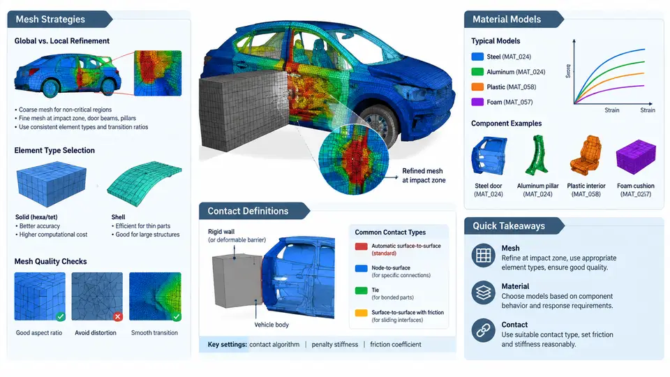
Side impact is one of the most demanding load cases in occupant safety simulation. The deformation path is short, the loading is highly localized, and the occupant sits only a few hundred millimeters from the striking barrier. A finite element (FE) model that performs acceptably in frontal crash may still produce non-physical intrusion in side impact if mesh density, material strain-rate behavior, and contact definitions are not deliberately engineered. This section treats the three modeling pillars that dominate side-impact fidelity: mesh strategy, material models, and contact definitions.
Coordinate Convention and Model Architecture
Before any meshing decision, fix the reference frame. In this course we adopt the standard SAE vehicle coordinate system: X forward, Y to the left, Z upward, with the origin at the vehicle datum. The striking barrier approaches along +Y for a left-side impact (or −Y for a right-side impact). All intrusion values, velocities, and contact normals in this chapter follow this convention; if a model is delivered in a different frame, transform it before comparison.
A typical side-impact occupant model is assembled from four subsystems: the vehicle body (B-pillar, rocker, door inner/outer panels, roof rail, floor), the door trim and armrest, the seat, and the occupant restraint system (side airbag, curtain airbag, seat belt, pretensioner). The barrier is usually a rigid or deformable moving wall (e.g., the EEVC/AE-MDB or IIHS moving deformable barrier). Each subsystem has different mesh and material requirements, so treat them separately rather than applying one global mesh size.
Mesh Strategies for Side Impact
Side impact is dominated by bending and local buckling of thin-walled closed sections — the B-pillar, rocker, and door beams. These members carry the intrusion load, so their mesh must resolve through-thickness bending and local wrinkling. Practical guidance:
- Shell elements for thin-walled body structures. Use fully integrated or reduced-integration shell elements (e.g., LS-DYNA
*SECTION_SHELLwith ELFORM 2 or 16) with at least 5 through-thickness integration points. Five points capture the elastic-plastic bending gradient; three points are usually insufficient once the section yields. - Target element size 5–8 mm on the B-pillar, rocker, and door beams. Coarser than 10 mm loses the local buckle wavelength and under-predicts intrusion. Refine to 3–5 mm in the impact zone and around spot welds.
- Spot welds and structural joints. Represent spot welds with tied contact or beam/hexa weld elements at the actual weld pitch (typically 25–50 mm). Weld failure is a primary intrusion mechanism; a rigid tie that never releases will over-stiffen the joint and under-predict intrusion.
- Hexahedral solids for thick castings and closures. Cast nodes, hinge reinforcements, and latch strikers benefit from solid elements; avoid forcing shells onto thick, three-dimensional geometry.
- Hourglass control. Reduced-integration shells are prone to hourglassing under the concentrated side load. Use stiffness-based hourglass control (e.g.,
IHQ=4with a coefficient around 0.05–0.10) and verify that hourglass energy stays below roughly 5% of internal energy.
A useful sanity check before running the full model: apply a quasi-static lateral patch load to the bare B-pillar and confirm the force–displacement curve is smooth and mesh-converged. If doubling the mesh density changes peak force by more than about 5%, the mesh is not yet adequate for intrusion prediction.
Material Models
Side-impact strain rates in the B-pillar and rocker reach the order of 10–100 s⁻¹, so rate-independent plasticity is not acceptable for the main structural members. Select material models by function:
| Component | Recommended model | Key parameters |
|---|---|---|
| B-pillar, rocker (HSLA / AHSS) | Piecewise-linear plasticity with rate effects (*MAT_024 + *MAT_ADD_STRAIN_RATE, or *MAT_081) | True stress–plastic strain curve, Cowper–Symonds or tabulated rate factor, failure strain |
| Door outer panel (mild steel) | Elasto-plastic shell (*MAT_024) | Yield ~180–250 MPa, moderate hardening |
| Aluminum door beam / extrusion | Anisotropic or isotropic plasticity with rate (*MAT_103 / *MAT_024) | Direction-dependent yield, rate sensitivity |
| Foam / energy absorber in trim | Crushable foam (*MAT_063 or *MAT_057) | Plateau stress, densification strain, hysteresis |
| Airbag fabric | Fabric membrane (*MAT_034 or *MAT_FABRIC) | Young's modulus, permeability, mass per area |
Two failure-modeling cautions matter in side impact. First, do not rely on a single element erosion strain to represent tearing; calibrate the failure strain against a coupon or component test, and use a damage-based or stress-state-dependent criterion where available. Second, verify that the material card's units are consistent — a mixed mm–tonne–s–N system is common in LS-DYNA, and a stress entered in MPa while the model expects GPa will silently produce a soft, over-intruding structure.
Contact Definitions
Contact is where side-impact models most often fail silently. The occupant, door trim, airbag, and barrier all interact within a narrow gap, and a missed or over-stiff contact changes the load path entirely.
- Barrier-to-vehicle contact. Use a surface-to-surface penalty contact (
*CONTACT_AUTOMATIC_SURFACE_TO_SURFACE) with the barrier as master and the door outer panel as slave. Set a friction coefficient around 0.3–0.5 for painted steel against the barrier face. - Door trim-to-occupant contact. Use
*CONTACT_AUTOMATIC_SURFACE_TO_SURFACEor a single-surface contact with a soft constraint penalty to avoid spurious spikes when the dummy's soft tissue compresses against the trim. Define the dummy as slave and the trim as master. - Airbag-to-occupant and airbag self-contact. Use
*CONTACT_AUTOMATIC_SINGLE_SURFACEfor the airbag fabric, and a dedicated airbag contact for the bag-to-dummy interface. Ensure the airbag's initial gap is closed by the inflator pressure ramp, not by an artificial initial penetration. - Self-contact of collapsing structure. The B-pillar folding onto the rocker and the door inner panel folding onto the seat require single-surface self-contact on the body structure. Without it, elements pass through each other and intrusion is under-predicted.
SSID/MSID sets and confirm the dummy's outer surface is included as a slave segment set.
Putting the Three Pillars Together
The figure below summarizes how mesh, material, and contact decisions propagate into the intrusion and occupant response. Read it as a dependency map: a coarse B-pillar mesh or a rate-independent material softens the structure, which increases intrusion, which in turn changes the trim-to-occupant contact timing and the airbag's effective standoff.
Verification Before Occupant Calibration
Do not begin restraint calibration until the structural model passes three checks. First, energy balance: total energy should be conserved to within a few percent, and hourglass energy should remain below 5% of internal energy. Second, intrusion correlation: compare simulated B-pillar and door inner-panel intrusion at 30, 60, and 90 ms against sled or full-vehicle test data; a systematic offset usually points to a material rate factor or weld representation error. Third, contact penetration: inspect the animation and the contact energy output for visible interpenetration of the trim into the dummy or of the folding structure into itself. Only after these pass should airbag timing, venting, and belt pretensioner parameters be tuned — otherwise the calibration will compensate for structural modeling errors and will not transfer to the physical vehicle.