4. Barrier and impactor modeling
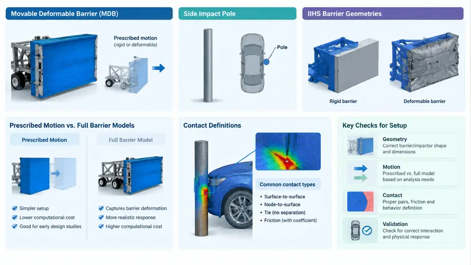
In a side impact simulation, the barrier or impactor is not a passive prop; it is the primary energy source and the dominant boundary condition of the entire event. The accuracy of the occupant response — chest deflection, pelvic force, head excursion — depends as much on how the striking object is modeled as on the restraint system itself. This chapter examines the three impactor families that dominate regulatory and consumer side-impact testing, the two fundamentally different ways of driving them (prescribed motion versus full barrier models), and the contact definitions that determine whether the interaction is physically credible.
4.1 The Three Impactor Families
Movable Deformable Barrier (MDB). The MDB is the workhorse of side-impact regulation (ECE R95, FMVSS 214 oblique, and the older FMVSS 214 perpendicular configuration). It consists of a rigid trolley carrying a deformable honeycomb/aluminum face. The critical modeling detail is the face: the honeycomb is anisotropic and crush-strength-calibrated, so it must be represented either by a calibrated *MAT_CRUSHABLE_FOAM / *MAT_HONEYCOMB material with direction-dependent yield stresses, or by a detailed cell-level model when face deformation patterns matter. The trolley mass (typically 950 kg for ECE R95, 1360 kg for FMVSS 214) and the impact velocity (50 km/h for ECE R95, 54 km/h for FMVSS 214) are prescribed test parameters, not free variables. The face height and ground clearance define the vertical load path into the struck vehicle's door, sill, and B-pillar — a 50 mm error in face height can shift the load path from the rocker into the door skin and change occupant loading substantially.
Side Impact Pole. The pole is a rigid, non-deforming cylinder (typically 254 mm diameter for FMVSS 201 / ECE R95 pole tests, 273 mm for some IIHS configurations) mounted on a rigid base. Because it does not crush, all deformation is absorbed by the struck vehicle. The pole test is the most severe localized loading case: a narrow contact patch concentrates force on the door, B-pillar, and often the occupant's chest directly. Modeling requirements are deceptively simple — a rigid cylinder with a defined radius, orientation, and impact angle — but the pole's *position relative to the occupant H-point* is the single most sensitive parameter. A 25 mm longitudinal shift of the pole can move the contact from the door beam to the door skin and change chest deflection by tens of millimeters.
IIHS Barrier Geometries. The Insurance Institute for Highway Safety uses two distinct side configurations. The side impact test employs a 1500 kg MDB with a specific face geometry (a 330 mm high, 1676 mm wide face with a 25° angled lower section) striking at 50 km/h. The side pole test uses a 254 mm rigid pole at 32 km/h with the vehicle moving at a 75° angle. The IIHS MDB face is deliberately shaped to load the door at two heights — a lower rail and an upper rail — which produces a characteristic two-lobe deformation pattern. Reproducing this pattern requires the face geometry to be modeled explicitly, not approximated by a flat plate.
4.2 Prescribed Motion versus Full Barrier Models
There are two ways to bring the barrier into contact with the vehicle, and the choice has major consequences for both fidelity and cost.
Prescribed motion (also called *BOUNDARY_PRESCRIBED_MOTION or kinematic barrier) imposes a velocity or displacement curve on the barrier's rigid body. The barrier is typically modeled as a rigid shell or a rigid body with a deformable face, and its motion is driven by a time-history curve rather than by an initial velocity plus contact forces. This approach is fast, numerically stable, and ideal for parametric studies where the barrier trajectory is known and the vehicle's response is the only unknown. Its limitation is that the barrier cannot react to the vehicle: if the struck vehicle's door is unusually stiff, a prescribed-motion barrier will penetrate it at the prescribed rate regardless of the actual contact force, producing non-physical local deformation and potentially over-predicting occupant loading.
Full barrier models give the barrier mass, an initial velocity, and a free rigid-body degree of freedom (usually translation along the impact axis, sometimes with a rotational DOF for angled impacts). The barrier decelerates according to the contact forces it experiences, exactly as in the physical test. This is the correct choice whenever the barrier's own dynamics matter — which is almost always for MDB tests, where the honeycomb crush and trolley deceleration are part of the measured event. The cost is higher: the barrier must be meshed, its mass and inertia must be correct, and the contact must be stable enough to handle the initial impact transient.
A practical hybrid is common in industry: a full barrier model with a rigid trolley and a deformable face, where the trolley's translational DOF is free but its rotational DOFs are constrained to match the test rig's guidance. This captures the essential physics (barrier deceleration, face crush) while avoiding the cost and instability of a fully free six-DOF barrier.
4.3 Contact Definitions
Contact between barrier and vehicle is where most side-impact models fail silently. Three definitions deserve explicit attention.
Barrier-to-vehicle contact. Use a surface-to-surface contact with the barrier face as the master and the vehicle exterior (door, sill, B-pillar, roof rail) as the slave. The barrier face mesh must be fine enough to resolve the honeycomb crush pattern — typically 10–15 mm element size — and the contact thickness must be set to zero on the barrier face if the face is modeled with solid elements, to avoid an artificial gap. Friction is usually set low (μ ≈ 0.1–0.2) because the honeycomb face crushes rather than slides; excessive friction will artificially couple the barrier to the door and distort the load path.
Self-contact within the barrier face. As the honeycomb crushes, folded cells can interpenetrate. A single-surface contact on the face with a small penalty stiffness prevents this without adding significant cost. Without it, the face can "tunnel" through itself and produce a non-physical force spike at peak crush.
Vehicle interior contact. The struck vehicle's door trim, armrest, and B-pillar trim contact the occupant's pelvis, chest, and head. These contacts must use the same friction and penalty settings as the barrier contact, and the trim must be modeled with realistic thickness and stiffness. A rigid trim model will over-predict occupant loading; a too-soft trim model will under-predict it and mask restraint deficiencies.
4.4 A Reproducible Configuration Example
Consider an ECE R95 MDB simulation. The barrier model is a full barrier with a rigid trolley (950 kg) and a deformable honeycomb face. The trolley is given an initial velocity of 50 km/h along the global X-axis, with translational DOF free and rotational DOF constrained. The face uses *MAT_HONEYCOMB with crush stresses of 0.35 MPa (X), 0.55 MPa (Y), and 0.90 MPa (Z), calibrated to the certification honeycomb. Contact is defined as:
*CONTACT_AUTOMATIC_SURFACE_TO_SURFACE
$  slave (vehicle)        master (barrier face)
   2000001                 3000001
$  fs        fd        dc        vc        vdc
   0.15      0.15      0.0       0.0       0.0
$  penmax    bt        dt        dmin      dmax
   0.0       0.0       1.0E-3    0.0       0.0
$  sfs       sfm       sst       mst
   1.0       1.0       0.0       0.0
Run the model and inspect three verification signals before trusting any occupant result. First, the barrier trolley's X-velocity should decay from 50 km/h to roughly 20–30 km/h over the first 40–60 ms, depending on vehicle stiffness; a decay to near zero within 20 ms indicates the barrier is too stiff or the contact penalty is too high. Second, the honeycomb face's crush depth should reach 200–350 mm at peak, with a smooth force–displacement curve; a jagged curve with spikes above 1.5× the nominal crush stress indicates self-contact failure or element distortion. Third, the door inner panel's intrusion velocity should peak at 8–12 m/s and then decay; a sustained high intrusion velocity after 60 ms suggests the barrier is still pushing through a collapsed structure, which usually means the door beam model has failed prematurely.
4.5 Choosing the Right Approach
Use prescribed motion when the barrier trajectory is well characterized and the study is parametric — for example, a design-of-experiments sweep on door beam gauge or B-pillar reinforcement, where the barrier's own dynamics are not the variable of interest. Use a full barrier model for certification, correlation against physical test data, and any case where the barrier's deceleration or face crush is part of the measured response. For pole impacts, the pole is always rigid and its motion is prescribed (the vehicle moves into it, or the pole moves at a prescribed velocity); the modeling effort belongs on the vehicle side, particularly the pole-to-door contact and the occupant-to-trim contact. In all cases, document the barrier mass, velocity, face geometry, and contact parameters alongside the model, because these are the parameters most likely to be silently altered when a model is reused across programs.