1. Side impact crash simulation fundamental
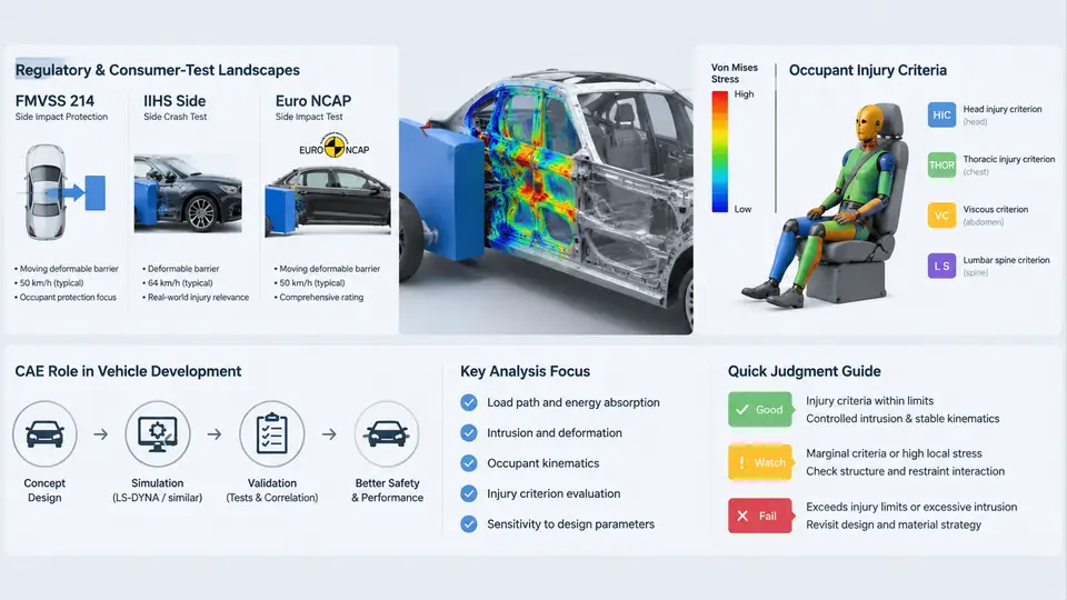
Side impact is one of the most demanding load cases in vehicle safety engineering. Unlike frontal crashes, where a long crumple zone absorbs energy progressively, a side impact offers only 200–350 mm between the struck door's outer skin and the occupant's pelvis. The barrier strikes at 50–60 km/h, and the occupant experiences the intrusion within 30–50 ms. This geometric and temporal compression is why side impact protection depends far more on structural design and restraint timing than on energy absorption alone — and why CAE plays a decisive role in getting it right before a single prototype is built.
The Regulatory and Consumer-Test Landscape
Three test families dominate global side impact development, and each imposes different boundary conditions on the simulation model.
FMVSS 214 (United States, regulatory) uses two distinct configurations. The barrier test (static/dynamic) drives a rigid, honeycomb-faced moving deformable barrier (MDB) at 53.9 km/h (33.5 mph) into the stationary vehicle at 90°, with the barrier's longitudinal axis perpendicular to the vehicle. The MDB weighs 1,368 kg and its face is 1,676 mm wide. The pole test (added in 2007) propels the vehicle sideways at 32 km/h (20 mph) into a rigid 254 mm diameter pole at 75° to the vehicle's longitudinal axis, targeting head and torso protection. FMVSS 214 is pass/fail against injury criteria, not a star rating.
IIHS side impact (United States, consumer) historically used a 1,500 kg MDB at 50 km/h with a barrier face raised to 759 mm ground height to represent an SUV striking a passenger car. The updated IIHS protocol (2020+) increased barrier mass to 1,900 kg and impact speed to 60 km/h, with a geometry that better represents a modern pickup or large SUV. IIHS reports a four-level rating (Good/Acceptable/Marginal/Poor) based on measured dummy injury values and structural intrusion.
Euro NCAP side impact (Europe, consumer) combines a 1,300 kg MDB at 60 km/h (mobile progressive deformable barrier, MPDB, in the latest protocol) with a 32 km/h oblique pole test at 75°. Euro NCAP also evaluates far-side occupant protection (the occupant on the side opposite the impact) and post-crash rescue/extrication. The MPDB uses a progressively deformable honeycomb face to produce a more realistic force–deflection characteristic than a uniform block.
| Protocol | Barrier / Mass | Speed | Key Focus | Output |
|---|---|---|---|---|
| FMVSS 214 barrier | Rigid MDB, 1,368 kg | 53.9 km/h, 90° | Near-side torso/pelvis | Pass/fail criteria |
| FMVSS 214 pole | Rigid pole, 254 mm | 32 km/h, 75° | Head/torso | Pass/fail criteria |
| IIHS (updated) | MDB, 1,900 kg | 60 km/h, 90° | Near-side + structure | Good→Poor rating |
| Euro NCAP MPDB | MPDB, 1,300 kg | 60 km/h, 90° | Near + far side | Points / star rating |
| Euro NCAP oblique pole | Rigid pole, 254 mm | 32 km/h, 75° | Head containment | Points / star rating |
Occupant Injury Criteria
Each protocol defines pass thresholds on dummy-measured responses. The most consequential for side impact are:
- HIC36 / HIC15 — Head Injury Criterion, integrating resultant head acceleration over the impact window. FMVSS 214 pole requires HIC ≤ 1,000; Euro NCAP applies HIC15 ≤ 700 for a 5-star head score.
- Thoracic Trauma Index (TTI) — used in FMVSS 214 barrier; combines upper and lower rib accelerations, weighted by mass and age. Threshold: TTI ≤ 85 for a 4-door passenger car.
- Rib deflection — Euro NCAP and IIHS measure chest compression (mm) via rib potentiometers on the WorldSID or ES-2re dummy. Euro NCAP high-performance limit is 22 mm; low-performance limit 42 mm.
- Acetabulum / pelvis force — pubic symphysis force and acetabular load measured on the pelvis of the side-impact dummy; thresholds around 3–4 kN depending on dummy and protocol.
- Far-side criteria — Euro NCAP now scores far-side occupant head excursion and shoulder-belt retention, requiring the dummy not to slip out of the belt or strike the opposite interior.
These criteria are not interchangeable across dummies. The ES-2re (FMVSS 214) and WorldSID 50th (Euro NCAP, IIHS) have different rib geometry, instrumentation and biofidelity, so a model validated against one dummy cannot be assumed accurate for the other without re-correlation.
Where CAE Fits in Vehicle Development
Side impact CAE is not a single simulation but a chain of models that mature alongside the design. In the concept phase, a coarse full-vehicle model (200–400k elements, 5–10 ms time step) screens body-in-white (BIW) topology: B-pillar reinforcement, rocker section, door beam and floor cross-member layout. As the design matures, the model is refined to 1–2 mm element size in the struck side, with detailed door trim, airbag modules and a validated dummy model. The final pre-test model typically runs 3–8 million elements and must reproduce barrier, dummy and restraint behavior within correlation tolerances before it is trusted to guide hardware decisions.
The practical value of CAE in side impact comes from three capabilities that physical testing cannot match: (1) parameter sweeps — running 50 variants of B-pillar gauge and grade in a weekend to find the mass-efficient reinforcement; (2) restraint timing optimization — tuning side airbag and curtain deployment timing against intrusion velocity profiles that vary by impact point; and (3) failure diagnosis — extracting section forces, hinge moments and intrusion velocity at the door trim to explain why a dummy response exceeded threshold, not just that it did.
A Reproducible Screening Example
Consider a concept-phase screening task: evaluate whether increasing the B-pillar inner reinforcement from 1.4 mm to 1.8 mm DP780 reduces peak door trim intrusion velocity below 8 m/s at the dummy pelvis location, without adding more than 1.2 kg. The model is a 350k-element full vehicle with the struck side at 8 mm average element size, an ES-2re dummy positioned per FMVSS 214, and a rigid MDB at 53.9 km/h. The run uses an explicit solver with a 1.5 μs stable time step and 120 ms termination time.
Two variants are submitted. The baseline (1.4 mm) shows peak intrusion velocity of 9.6 m/s at t = 42 ms and pelvis force of 3.8 kN, exceeding the 3.5 kN target. The 1.8 mm variant reduces peak velocity to 7.4 m/s and pelvis force to 3.1 kN, but adds 1.6 kg — over the mass budget. The engineer then checks a tailored 1.6 mm DP780 with a local 2.0 mm patch at the pelvis load path, which lands at 7.9 m/s and 3.3 kN with 1.1 kg added. This is the kind of trade study that would take weeks of hardware iteration but runs in a day of CAE — and it is only credible if the underlying model has been correlated against a physical barrier test at the same configuration.
The remainder of this course builds directly on these foundations: barrier and dummy modeling, material and connection fidelity on the struck side, restraint deployment logic, and the correlation workflow that turns a simulation into a decision-making tool. The regulatory and consumer landscape described here defines the targets; the injury criteria define the pass/fail language; and the CAE chain defines how engineering teams move from concept to a correlated, sign-off-ready model.