1. Side and curtain airbag system architect
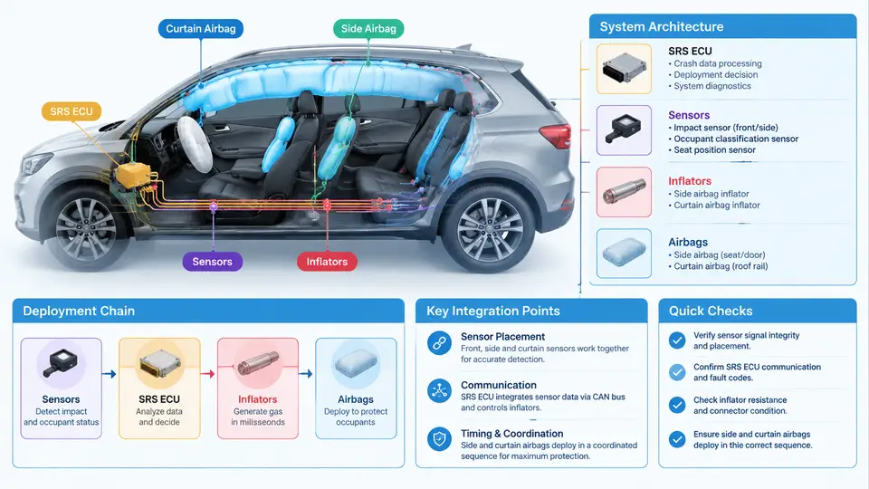
Side-impact protection is fundamentally different from frontal protection. The lateral crumple zone is short — often only 200–400 mm between the door trim and the occupant's pelvis — and the time available for restraint action is correspondingly compressed. A frontal crash may allow 30–50 ms from impact to full bag inflation; a pole or barrier side impact can demand that the side airbag reach full pressure in under 15 ms. This timing pressure is what shapes the entire side and curtain airbag architecture: sensors must be closer to the impact, the deployment decision must be made faster, and the inflator must fill a smaller, more constrained volume with high mass flow.
This chapter establishes the system-level view. It describes what components make up a side/curtain airbag system, where they sit in the vehicle, how sensing is distributed and integrated, and how a detection event propagates through the deployment chain to a fired restraint. Later chapters build on this foundation with calibration, performance targets, and validation methods.
Component inventory and physical layout
A modern side protection system typically comprises four functional groups:
- Restraint modules — side airbags (thorax, pelvis, or combined thorax-pelvis) mounted in the seat back or door module, and curtain airbags running along the roof rail from the A-pillar to the C-pillar (or further back in three-row vehicles).
- Inflators — pyrotechnic or hybrid gas generators. Side thorax inflators are usually compact cylinders inside the seat frame; curtain inflators are larger and often mounted at the C-pillar or roof rail, feeding a fill tube that distributes gas along the cushion length.
- Sensing elements — peripheral pressure sensors in the front doors, acceleration sensors on the B-pillar or rocker, and the central airbag control unit (ACU) with its own internal accelerometer and safing logic.
- Interconnect and diagnostics — a dedicated airbag bus or discrete wiring harness, squib connectors with shorting clips, and the diagnostic link that reports fault codes and deployment loop status.
Layout decisions are driven by the crash modes the vehicle must cover: FMVSS 214 oblique pole, ECE R95 barrier, side pole at 32 km/h, and the IIHS 2.0 side rating with its higher-energy moving deformable barrier. A curtain that stops at the B-pillar leaves rear-row heads exposed in a pole strike; a thorax bag mounted in the door rather than the seat loses position accuracy when the seat is reclined. These are architecture-level trade-offs, not calibration details.
Sensor integration: pressure, acceleration, and safing
Side sensing relies on two complementary physical principles. Door pressure sensors measure the rapid rise in cabin pressure when the door outer panel is pushed inward — the door cavity acts as a crude but fast transducer, and pressure rise occurs within a few milliseconds of intrusion. B-pillar or rocker accelerometers measure lateral deceleration of the body structure and are less sensitive to door trim compliance but slower to respond to localized pole impacts. Combining both gives a robust, fast, and discriminating detection front.
The ACU performs the arbitration. It applies a crash algorithm — typically a velocity-change integration with thresholds and time windows — and requires agreement between a "fire" sensor and a safing sensor. The safing function exists to prevent inadvertent deployment from a single sensor fault or electromagnetic disturbance: the squib circuit is only armed when the safing criterion is also satisfied. In side systems, the safing sensor is often the ACU's internal lateral accelerometer, while the peripheral pressure sensor provides the fast primary signal.
The deployment chain, end to end
The chain from impact to inflated cushion has a fixed sequence with measurable latencies at each stage:
- Intrusion and signal generation — the barrier contacts the door; the pressure sensor diaphragm deflects and outputs an analog or digital signal within roughly 1–3 ms.
- Signal conditioning and plausibility — the ACU filters, digitizes, and checks the signal against plausibility windows (rate of rise, amplitude, cross-channel consistency).
- Algorithm decision — the crash algorithm evaluates the combined sensor set and issues a deployment request when thresholds are crossed within the valid time window.
- Safing confirmation — the independent safing path must also be satisfied; otherwise the request is inhibited.
- Squib firing — the ACU discharges a firing capacitor through the squib, igniting the gas generant. Loop resistance is monitored continuously; a squib outside the specified resistance window (commonly 1.7–2.5 Ω at 20 °C for many designs) will set a fault and may inhibit deployment.
- Inflation — gas fills the cushion; a thorax bag may reach working pressure in 8–12 ms, a curtain in 15–25 ms depending on volume and inflator output.
The figure below maps this chain as a signal and energy flow, showing where sensing, arbitration, and actuation sit relative to each other and where the safing path runs in parallel with the primary decision path.
Integration constraints that shape the architecture
Three integration realities dominate design reviews. First, seat-mounted versus door-mounted side bags: seat mounting keeps the bag positioned correctly as the seat moves, but routes the harness through the seat and requires a robust connector that survives seat travel; door mounting simplifies wiring but couples bag position to door trim deformation. Second, curtain coverage and the fill tube: the cushion must remain inflated for roughly 3–5 seconds to protect against ejection in a rollover, which means the inflator and cushion seam design must balance initial fill speed against sustained pressure. Third, occupant detection interaction: passenger presence and position sensing can suppress a side bag on an unoccupied seat, but suppression logic must never delay deployment on an occupied seat — the timing budget does not allow it.
A practical check when reviewing any side airbag architecture is to trace one specific crash mode end to end. Take the FMVSS 214 oblique pole test at 32 km/h: confirm which sensor sees the intrusion first, what the expected pressure rise rate is, whether the safing path will be satisfied within the algorithm's time window, and which modules are commanded. If any link in that chain is ambiguous on the wiring diagram or in the calibration document, the architecture has a gap that will surface during validation.
With the component layout, sensing front, and deployment chain established, subsequent chapters can treat calibration thresholds, cushion geometry, and validation test matrices as refinements of this architecture rather than independent topics.